Remote Flying Fish Project Part 9: Soldering and Arduino Programming
Follow article Dave from DesignSpark
How do you feel about this article? Help us to provide better content for you.
Dave from DesignSpark
Thank you! Your feedback has been received.
Dave from DesignSpark
There was a problem submitting your feedback, please try again later.
Dave from DesignSpark
What do you think of this article?
After getting the pieces of PCB ready from the manufacturer, now is time to get into the final part to get everything combined.
For soldering, you will need to prepare AT LEAST four kinds of tools:
1. Soldering Iron (with a stand of course, or you might easily cause unwanted accidents)
2. Soldering wire
3. Tweezer (SMD components are too small for the human hand to efficiently process with them)
4. Piler cutter
Other tools like wire stripper, flux, desoldering braid, desoldering pump, heat gun and so on, are all optional to me.
Here is a good starting tutorial worth taking a look at.
PCB is usually the most common part to encounter errors and requires a lot of retries. If you are already in the loop, don't worry, there is an alternative which I will tell you about later.
For our board, there are several tweak points to pay attention to:
1. Angle of the joint between the wing parts and main PCB
2. Angle of the DC motors installed onto the wing parts
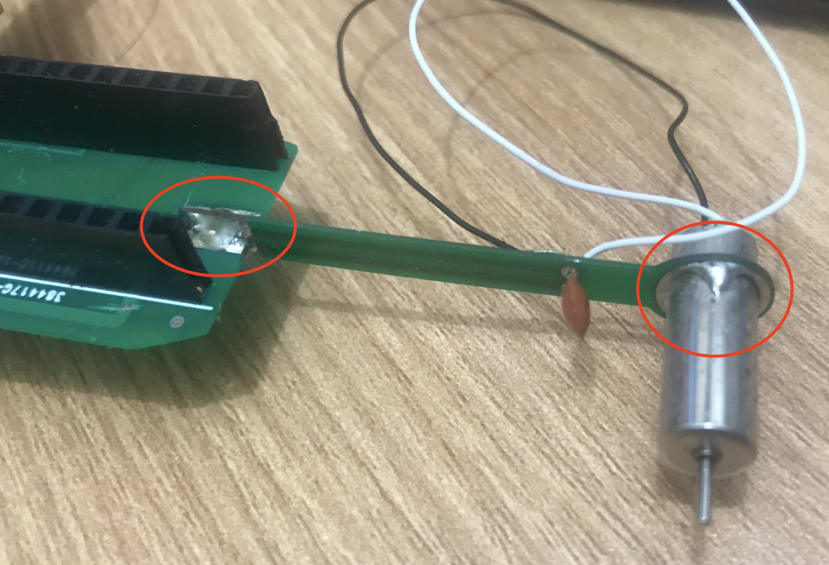
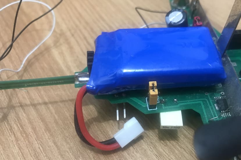
3. Battery positioning
After soldering work is done, the object will look something like this.
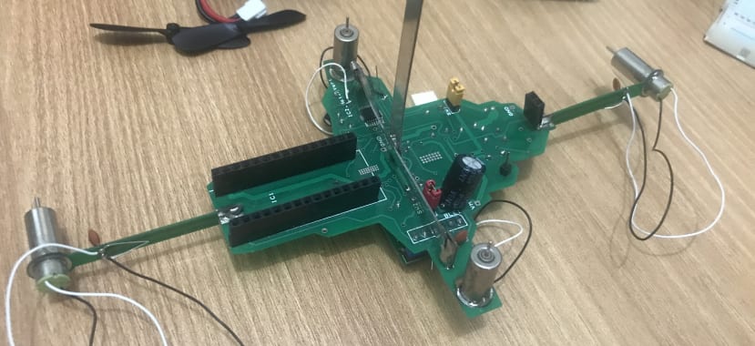
From time to time, we should use a DMM to perform continuity tests during the soldering process, to ensure the soldered pins are well connected with the circuit.
Now we can try to connect the battery and put all the shunts on to check if power is delivered to the Arduino board and BLE module successfully.
Now you should see the lights on right!? Great, now to move to the next step: Arduino programming.
The logic of Arduino programming is kind of easy as there are only two parts we want to handle control:
1. Bluetooth Connection
2. Motor Control
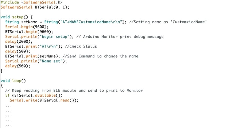
So, similar to chapter 3-5, we will be using analogWrite and SoftwareSerial to complete our programme.
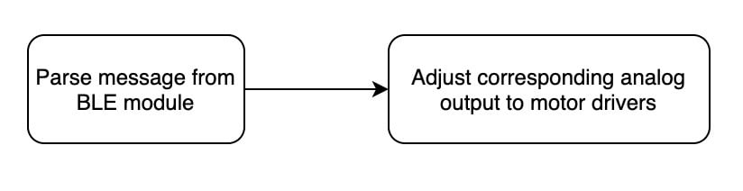
Here is the logic of operation:
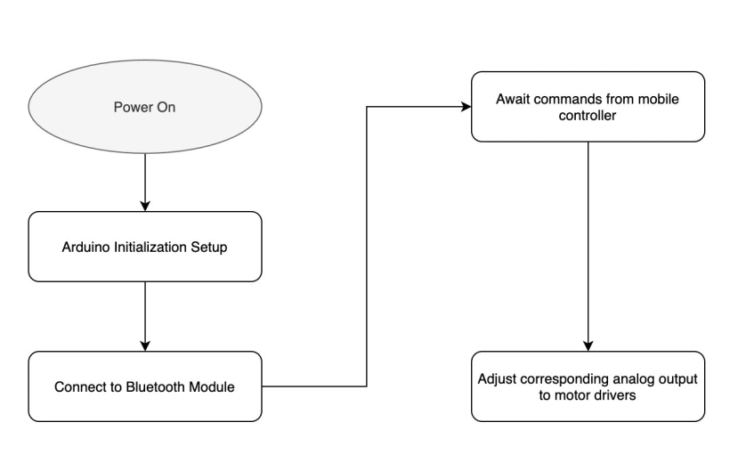
Here is a programme setup excerpt:
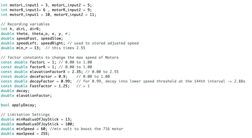
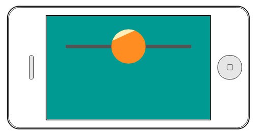
The 20+ variables are used for a different kind of micro-adjustment of a simulated joystick controller output, which I am not elaborating on here. To make things clearer, consider your input a slider with origin at the centre. Then the motors should rotate clockwise or anticlockwise depending on the difference of slider value from the central one.
For the skipped part in loop(), the looping logic would be like this:
To make things simple, you can also use RemoteXY, which simply paste the code like we did in early chapters and change the analogue output accordingly to the RemoteXY parameters.
This part is worth trying a lot to add different variations to your outcome, so I am not explaining too much here to allow you to better brainstorm your own design.
Just remember one thing, if you encountered any errors on software ground, print out some messages and trim them down into functional chunks. Completing the tasks bit by bit will eventually lead you to the goal.
In the next chapter, we will move on deeper with some advanced ways of doing it.
You can download the pdf version of this chapter in the Download section below.
Parts in this series
- Remote Flying Fish Project Part 1: Introduction
- Remote Flying Fish Project Part 2: DIY Series - Arduino Testing
- Remote Flying Fish Project Part 3: Motor Testing
- Remote Flying Fish Project Part 4: Bluetooth Testing
- Remote Flying Fish Project Part 5: Motor Testing with Remote XY
- Remote Flying Fish Project Part 6: PCB Design (preparatory)
- Remote Flying Fish Project Part 7: PCB Design (Schematic)
- Remote Flying Fish Project Part 8: PCB Design (PCB Layout)
- Remote Flying Fish Project Part 9: Soldering and Arduino Programming
- Remote Flying Fish Project Part 10: Flutter Introduction
- Remote Flying Fish Project Part 11: Flutter Installation on MacOS
- Remote Flying Fish Project Part 12: Flutter Installation on Windows