Remote Flying Fish Project Part 3: Motor Testing
Follow article Dave from DesignSpark
How do you feel about this article? Help us to provide better content for you.
Dave from DesignSpark
Thank you! Your feedback has been received.
Dave from DesignSpark
There was a problem submitting your feedback, please try again later.
Dave from DesignSpark
What do you think of this article?
And now, it is time to start with the motor part.
No matter which model of motor you decided to purchase, make sure it works under-voltage ~3.3V to 10V.
In the project, Texas Instruments DRV8833CPWP Motor Driver IC is being selected as the motor driver.
And luckily, there is a development kit (184-0471) of this driver available. As a result, we can do testing more efficiently.
Or if you believe in the redundancy of the kit, you might only test the functionality of the motors.
Objectives:
Here are the objectives of this chapter:
- Examine the functionality of the motors
- Try controlling motor speed through Arduino
Component requirements:
- Either one:
- two DC supply
- 5V USB plug with > 1A rated current, plus DC-DC converter
- Male-to-female Dupont lines
- DRV8833 Development Kit
- Coreless motor 8520
- Arduino Nano
Procedures for examining the functionality of the motors
!! Be careful, the temperature of the coreless
motor will increase with time !!
- Hold your motor tight
- Connect the two-terminal inputs of the motor to the power supply.
- Power on
- Reverse the +- connection and try again.
By then, you are expected to see the motor revolving in both clockwise and anti-clockwise state.
Procedures for controlling motor speed through Arduino:
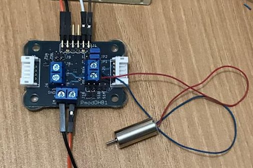
- Connect the motor and the development kit as shown in the diagram
**Connect VCC -> 5V (1st power supply), GND -> ground, DIR -> D5(Arduino), EN -> D9(Arduino), VM -> 3.7V (2nd power supply), GND -> ground

- Burn the following code into your Arduino
void setup(){ digitalWrite(5,HIGH); analogWrite(9,255); // 5V analogWrite(10,204); // 4V analogWrite(11,153); // 3V } void loop(){} - Hold your motor tight
- Power on everything, change the EN pin from D9 to D11 to see the change in motor speed.
P.S. Be careful of the rising temperature over a period of time at the surface of the motors.
In the next part, we will talk about Bluetooth testing.
You can download the pdf version of this chapter in the Download section below.
Parts in this series
- Remote Flying Fish Project Part 1: Introduction
- Remote Flying Fish Project Part 2: DIY Series - Arduino Testing
- Remote Flying Fish Project Part 3: Motor Testing
- Remote Flying Fish Project Part 4: Bluetooth Testing
- Remote Flying Fish Project Part 5: Motor Testing with Remote XY
- Remote Flying Fish Project Part 6: PCB Design (preparatory)
- Remote Flying Fish Project Part 7: PCB Design (Schematic)
- Remote Flying Fish Project Part 8: PCB Design (PCB Layout)
- Remote Flying Fish Project Part 9: Soldering and Arduino Programming
- Remote Flying Fish Project Part 10: Flutter Introduction
- Remote Flying Fish Project Part 11: Flutter Installation on MacOS
- Remote Flying Fish Project Part 12: Flutter Installation on Windows