Remote Flying Fish Project Part 1: Introduction
Follow article Dave from DesignSpark
How do you feel about this article? Help us to provide better content for you.
Dave from DesignSpark
Thank you! Your feedback has been received.
Dave from DesignSpark
There was a problem submitting your feedback, please try again later.
Dave from DesignSpark
What do you think of this article?
Chapter 1
[Excerpt from AirSwimmer Official Video]
Are you looking for some fun? Have you ever imagined that you can make a fish fly in the air? If your answer is “yes”, here is what you are looking for. This is a series of tutorials guiding you on how to build a Bluetooth-controlled flying fish from scratch.
Here is a video excerpt of the prototype designed and built by City University of Hong Kong:
[Excerpt from CityU EE Summer Camp Video]
Getting Started
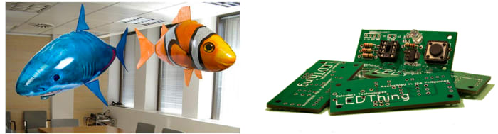
There are two helium-gas-filled fish-shaped balloons and several Printed Circuit Boards (PCBs) shown in the above figures. How would you relate these two things?
You probably know the answer – design an electronic system and mount it on the balloons, so that you can control the fish wherever you like.
Of course, the required components are not solely balloons and circuit boards. So, let’s get started with an overview.
NOTE: The components here are only for preliminary testing, instead of a full set. The detailed specification will be added in a later chapter.
Components List
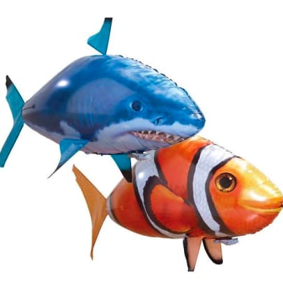
Fish-shaped balloon:
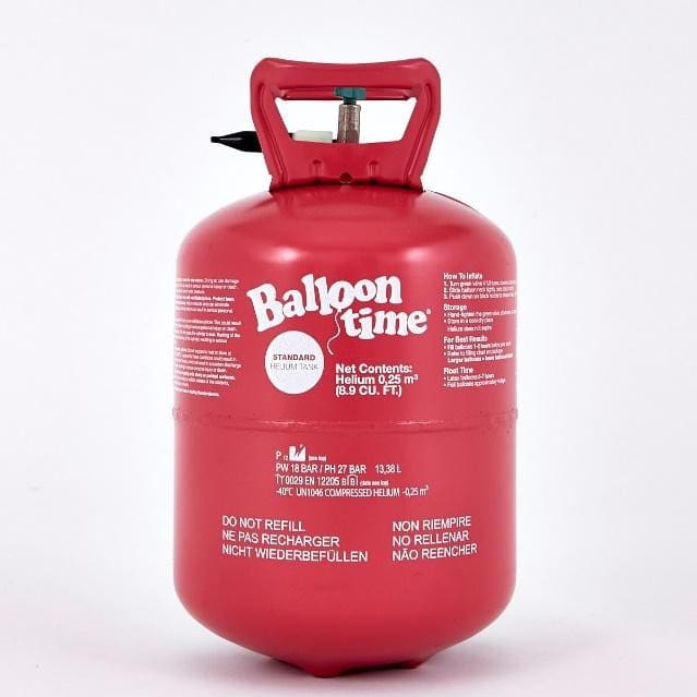
1. Helium balloon as big as Air Swimmer x 1 (length: ~52 inches, height: ~32 inches, width: ~30 inches)
2. Helium gas
3. Double-sided adhesive foam tapes
4. Transparent adhesive tape
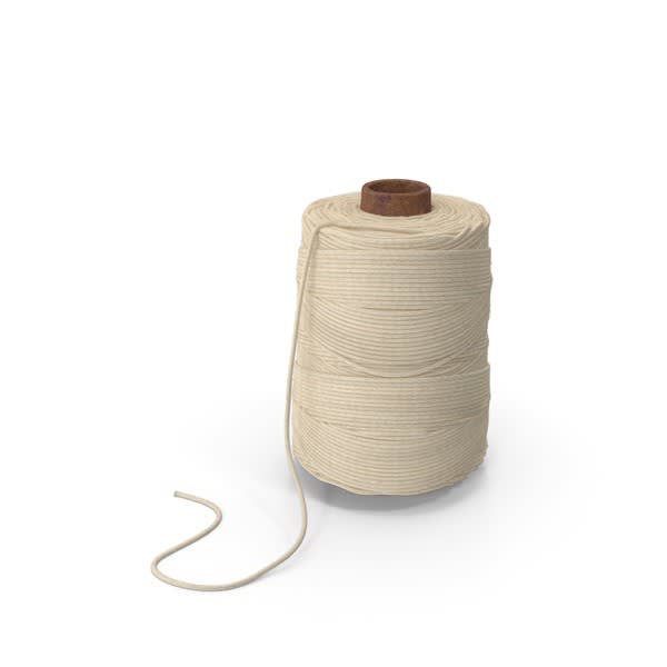
5. String
Circuit components used at the testing stage are listed here:
- Arduino Nano
(696-1667)
- Bluetooth 4.0+ module (HM-10 recommended)
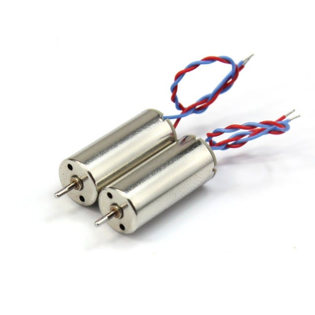
- 720 coreless motor (commonly available on e-shops)
- Motor driver DRV8833: development kit version, for motor functionality test (184-0471)
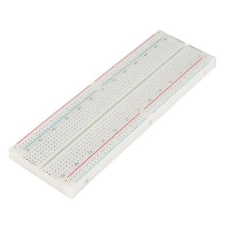
- Breadboard
(102-9147)
- Dupont wire male-to-male & female-to-male (10-20cm)


Circuit components used at the PCB(printed circuit board) implementation stage are listed here:
- DC-DC boost converter (790-2916)
- Motor driver IC DRV8833PWP (825-3120)
- SMT e-capacitors (detailed values to follow in Ch.7)
- Ceramic capacitors (detailed values to follow in Ch.7)
- SMT inductors (detailed values to follow in Ch.7)
- SMT resistors (detailed values to follow in Ch.7)
- Schottky diode (688-0502)
- 3.7V battery
- Male and female headers
Tools List:
- Soldering wire (the thinner the better)
- Soldering iron
- Digital multimeter (DMM)
- Other safety equipment (optional)
- Plastic screws (2mm/3mm diameter)


Now if you have all the components ready, let’s move on to the next step of motor testing with Arduino!
If you don't have them yet, or having difficulties in gathering all, just DON'T WORRY! You are free to make changes and try different things with what you have!
Next, we move on to the next chapter, Arduino Testing :)
You can download the pdf version of this chapter in the Download section below.
Parts in this series
- Remote Flying Fish Project Part 1: Introduction
- Remote Flying Fish Project Part 2: DIY Series - Arduino Testing
- Remote Flying Fish Project Part 3: Motor Testing
- Remote Flying Fish Project Part 4: Bluetooth Testing
- Remote Flying Fish Project Part 5: Motor Testing with Remote XY
- Remote Flying Fish Project Part 6: PCB Design (preparatory)
- Remote Flying Fish Project Part 7: PCB Design (Schematic)
- Remote Flying Fish Project Part 8: PCB Design (PCB Layout)
- Remote Flying Fish Project Part 9: Soldering and Arduino Programming
- Remote Flying Fish Project Part 10: Flutter Introduction
- Remote Flying Fish Project Part 11: Flutter Installation on MacOS
- Remote Flying Fish Project Part 12: Flutter Installation on Windows