Remote Flying Fish Project Part 2: DIY Series - Arduino Testing
Follow article Dave from DesignSpark
How do you feel about this article? Help us to provide better content for you.
Dave from DesignSpark
Thank you! Your feedback has been received.
Dave from DesignSpark
There was a problem submitting your feedback, please try again later.
Dave from DesignSpark
What do you think of this article?
Based on chapter 1, we now have a fish balloon, a tank of helium gas, several motors and motor drivers.
DO NOT inflate the balloon yet...

Just leave it like this...
Arduino testing
**If you are familiar with using Arduino, you may skip this chapter.**
Before testing, let’s get to know some of the background to Arduino.
Introduction
Arduino is an open-source electronics platform based on easy-to-use hardware and software. Arduino boards are able to read inputs, like the lights on a sensor and turn it into output in order to activate a motor, turn on an LED or publish something online. To do so, Arduino programming language and Arduino Software (IDE) will be required.
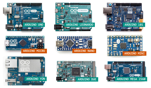
Types of Arduino
In the Arduino family, there are many different models of boards and modules with different supporting features, for example, Arduino UNO, NANO, MICRO, MEGA. In this project, every model can also perform similar results, it only needs to select the module in your Arduino IDE. We will discuss it in the following part.
Selection of Arduino board

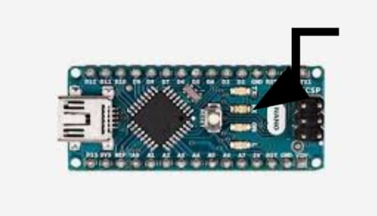
For the design of the product, you are recommended to use Arduino Nano. The pin configuration is as shown below.

Arduino Nano in total provides 22pins for data I/O (input/output), which are D0-D13 and A0-A7. For some pins, like D0, D1, D11, and D12, they serve for other purposes as well. If you do not know what they will do, you should not prioritize their usability.
Nevertheless, Nano is not the lightest or the smallest board in the Arduino series. You have other options regarding the design of the product and you are free to use other boards during development and testing.
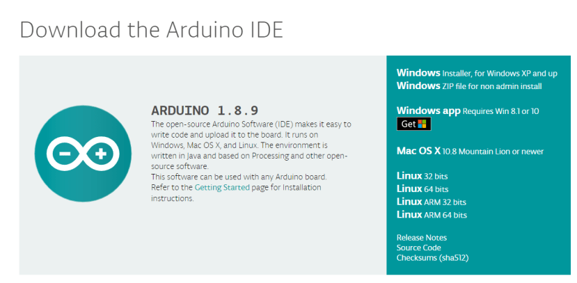
Installing the Arduino IDE
You need to install the Arduino Integrated Development Environment (IDE) on the computer. Although your computer might contain the Arduino IDE already, it is recommended to install the Arduino again to reduce the probability of errors during the whole development process. Get your computer ready by working on the following progress.
- Go to the official Arduino download page ( https://www.arduino.cc/en/Main/Software )
- Select the install packet depends on the operating system of your computer.
- A ZIP file will be downloaded to your computer. Unzip it and drag the folder inside to the desktop. Open the folder and open the application “arduino.exe”. Now Arduino IDE is available on your computer.
Setting up the Arduino IDE
- Connect the Arduino Nano to the computer using a Nano USB cable. (The version of USB cable depends on the module of Arduino board you are using. Wait until the initialization of the board finishes.
- Check the COM Port number of the Arduino Nano in your computer as follows:
(i) Click “Control Panel” at the Start Menu and click “Hardware and Sound”
(ii) A window will show up, choose “Device Manager” (under Devices and Printers).
(iii) If a pop-up message shows up, click ok.
(iv) A “Device Management” window will show up.
(v) Double click on “Ports (COM & LPT)”, check the parenthesis next to Arduino Nano. In this case, it is COM3.
- Start the Arduino IDE, check the settings:
(i) Board: Arduino Nano
(ii) Processor: ATmega328
(ii) Port: Choose the Port Number obtained in Step 2
(iii)Programmer: AVRISP mkII


Turning On the On-board Light
This part teaches you more about the interaction between programming instructions, Arduino board, and peripherals, for example, LED.
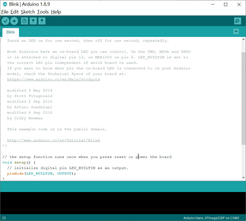
- Click on the “File” > “Examples” > “01. Blink. '' A new window showing a sketch named “Blink” should pop out as below. Just to note that in Arduino IDE, the source code is called a “sketch”.
- The pop-out sketch “Blink” should be the same as shown below. Study the comment inside “/* ... */” CAREFULLY. One should note that comment is widely used in programming since it provides useful information to people who read the program afterwards. In Arduino, we put the comment inside /* */ or after //. Lines inside /* */ or after // will not be executed by the program.
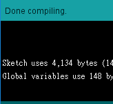
- Verify the sketch “Blink” by clicking the “✔” on the top right-hand corner. If there is no problem, Arduino will show a message as below.
- If there are any problems, Arduino will show an error message as below here. If an error message is shown, please try to debug the program by following the message.
- If compilation completes without errors, click the “→” to upload the sketch to the Arduino board. The Arduino board will be initialized and be installed with the sketch “Blink” after you upload the sketch.
- Wait until the word “Done uploading” shows on the status bar.
- Now observe the Arduino board, you should see the on-board LED marked “L” blinking.
- We can follow the sketch “Blink” to understand why the on-board LED blinks.
The program above shows how to set the LED “L” to be the output. There are other settings from Pin 0 to 13 which will be shown in the future part. You HAVE TO set the correct pin as an output so the signal can successfully go out from that pin.
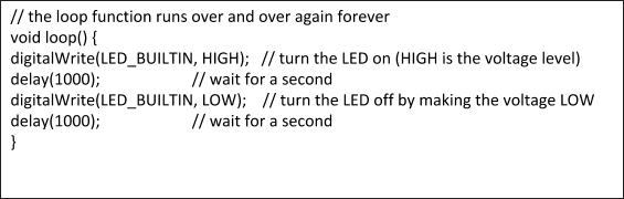
The program below shows a loop which means the program keeps going through the contents inside until there is any break (this program does not contain break). The instruction “digitalWrite” means giving a signal (HIGH or LOW) to the pin (LED_BUILTIN here). HIGH means applying power while LOW means no power is applied, and “delay” means holding everything. “1000” inside the bracket of “delay” means 1000 milliseconds (ms), which indicates 1000 x 10-3 second, i.e. 1 second.
- You can try to change the number 1000 to other amounts, for example, 400 or 2500. The command “delay” then holds 0.4 seconds and 2.5 seconds respectively. Upload the sketch to the Arduino board after you change the number.
- DO NOT change any settings. You need to use the blink as the template for completing the next part.


In the next chapter, we will cover, Motor Testing :)
You can download the pdf version of this chapter in the Download section below.
Parts in this series
- Remote Flying Fish Project Part 1: Introduction
- Remote Flying Fish Project Part 2: DIY Series - Arduino Testing
- Remote Flying Fish Project Part 3: Motor Testing
- Remote Flying Fish Project Part 4: Bluetooth Testing
- Remote Flying Fish Project Part 5: Motor Testing with Remote XY
- Remote Flying Fish Project Part 6: PCB Design (preparatory)
- Remote Flying Fish Project Part 7: PCB Design (Schematic)
- Remote Flying Fish Project Part 8: PCB Design (PCB Layout)
- Remote Flying Fish Project Part 9: Soldering and Arduino Programming
- Remote Flying Fish Project Part 10: Flutter Introduction
- Remote Flying Fish Project Part 11: Flutter Installation on MacOS
- Remote Flying Fish Project Part 12: Flutter Installation on Windows
Comments