Good Air Canary - Build Guide
Follow article
 Dave from DesignSpark
How do you feel about this article? Help us to provide better content for you.
Dave from DesignSpark
Thank you! Your feedback has been received.
Dave from DesignSpark
There was a problem submitting your feedback, please try again later.
Dave from DesignSpark
What do you think of this article?
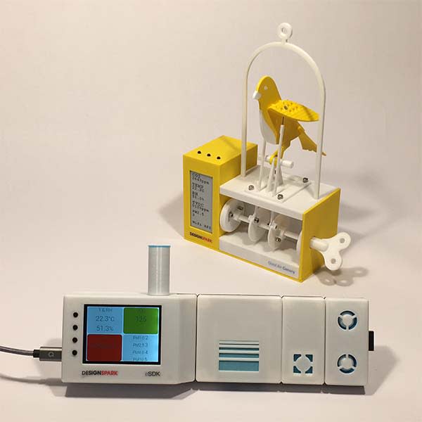
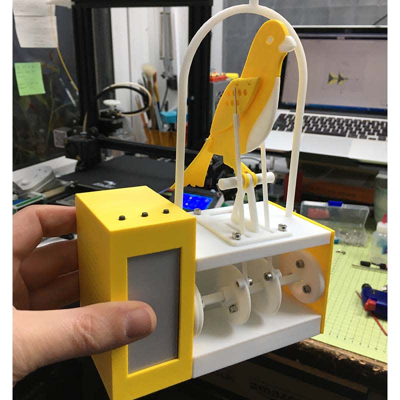
The Good Air Canary animates at different levels of air quality (from good to poor to bad to dangerous), and you can even record audio of it complaining that you need to open a window!
The ‘Good Air Canary’ evolved from the R&D phase of the Air Quality Kit (or DesignSpark Environmental Sensor Development Kit (ESDK) as it’s known). Amongst many other facts from speaking with leading experts on pollution through to industrial sensors - the most startling was that whilst working in my 2m-cubed shed, I was quite literally talking myself into poor respiratory and cognitive health. The notion that I was waffling on too much was of course not a shock to my wife, friends or anyone at RS who has worked with me - but in all seriousness, if you work in an average-sized home office with the doors and windows shut for an hour or two you are almost certainly trying to work at a level, health experts would not advise.
High CO2 levels reduce cognitive performance dramatically. Figure from Satish 2012.
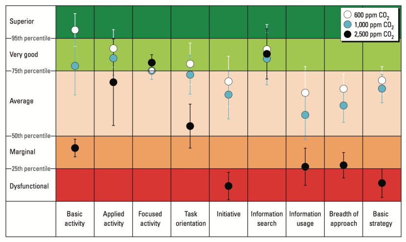
Studies from Harvard have shown that you are simply ‘stupider’ if you work in high CO2 environments. (More links). So what is ‘too high’? CO2 is measured in ppm (parts per million). Background CO2 outside is around 500ppm, and if indoors it gets to 1000ppm this is not good - and yet I can get myself to 4000ppm in my shed after only 1 hour of normal breathing (possibly sooner if on an exciting project zoom call!). I had a ‘techy’ looking CO2 Monitor, but all these ppm units feel rather alien to those outside of technical backgrounds. Hence wanting to make a fun gizmo to make it more relatable...
The old story of the ‘Canary in the Coalmine’ is pretty well known, but in case you’re unfamiliar - coal miners would use a canary as an ‘early warning gas detector’ - as it would fall off its perch if exposed to tiny amounts of toxic gas. Humans could then run back fast, as they can cope with more - but only slightly more. It was hard to detect as many toxic gasses in mines are tasteless and odourless. A nice aspect of researching this properly was that I learned someone made a ‘resuscitator’ - to bring the canary back from the brink of death.
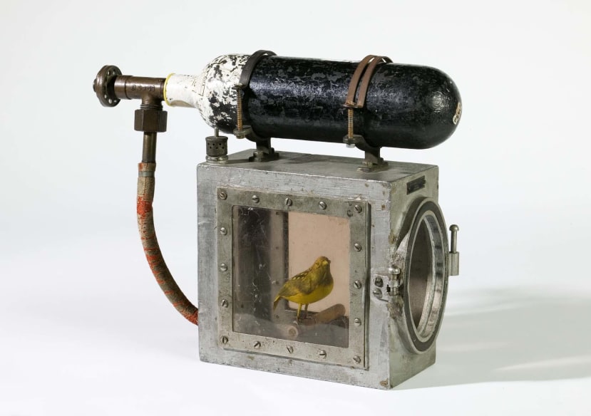
Cage for reviving canary, with oxygen cylinder, made by Siebe Gorman & Co. Ltd, London (https://museumcrush.org/)
I hope that this IoT Canary will bring you back from the ‘dead’ or ‘zombie’ like state we all experience from being in a stuffy room, but now the science really does give you the data to insist to your boss that you need to step outside and take a walk - not just for the good of your health, but truly your creative and professional output. The science shows you simply can’t think laterally at 4000ppm, so why fight it - open some windows and put your health first for better work/health balance.
The following DIY guide shows you not only how to build a charming desktop reminder, but the IoT functionality can be connected to any number of sensors of external data sources. The Canary could warn you about pollen counts, high winds, or forest fires - the choice is yours: It warns you you should take action about your environment, be it locally or indeed, globally.
This project works with the Air Quality ESDK Kit. I suggest if you are new to IoT you consider building this as well, but if you are experienced in IoT you can of course connect the Canary to any other data source of your choosing. Have fun either way!
Parts, Tools & Equipment.
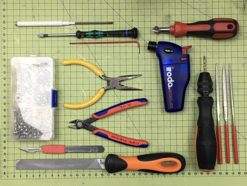
The Hand Tools shown here are pretty basic, and the intention is that you do not need any fancy workshops to build the structure of the Canary. In addition to this you will need to make a basic PCB, so you will need a soldering iron, and of course some basic prototyping board as well as a few components, but nothing requires any special PCB assembly (ie all through-hole soldering).
3D Printing:
- 3D Printer (or able to print files via LINK below).
- White PLA Filament (832-0223) (+ 1 Alternative Colour, e.g. Yellow (832-0232)
- Printer Nozzles of 0.6mm, though 0.4mm will also be fine.
Fixtures & Fittings:
- Brass Inserts - 1x 100 pack (027-8534)
- Hex M3 x 6mm Screws - 1x 50 pack (028-0981)
- CSK M3 x 6mm Screws - 1x 50 pack (304-4788)
- 4mm (dia) x 1mm (thick) Magnets (LINK)
Electronic Components:
- Servo 9g (215-3180)
- 2.9” Waveshare B/W eINK Screen (LINK)
- 5V Linear Voltage Regulator (168-6612)
- 1N4001 Diode, 1A, 5V (628-8931)
- 330nF Multilayer Ceramic Capacitor (801-5390)
- 100nF Multilayer Ceramic Capacitor (538-1203)
- DC Power Adaptor 9V, 1A (121-7145)
- DC Power Socket (048-7832)
- 3x Momentary Buttons 4.9mm (479-1485)
- Toggle Switch (734-7066)
- 3W Speaker (LINK1)(LINK2)
SBCs/Boards:
- Arduino Nano 33 IoT (192-7589)
- Adafruit 16-Channel 12-bit PWM/Servo Driver (LINK)
- Adafruit Audio FX Sound Board + 2x2W Amp (LINK)
- 70x90mm Double Sided Protoboard (LINK)
- 20x44mm Double Sided Protoboard (Likely as part of any set/stock of the above)
Consumables:
- Wire for PCB Wiring-up.
- SuperGlue (1x3g tube will be ample).
- Sellotape / Masking Tape.
- Cocktail Sticks.
- Sandpaper (suggested 400, 600, 1000 grit)
Generic Tools:
- Soldering Iron, Soder, etc.
- Mini Hand Files - Flat, Round, Square (for metal, and plastic filing).
- Mini Blowtorch (or soldering iron) - to insert Brass Inserts.
- Hex 2.5mm Key / Driver (for Screws).
- Scalpel / Craft Knife.
- Calipers.
- Hot Melt Glue Gun.
- Drill/Handdrill with 1.5mm, 3.0mm, 3.5mm, 4.0mm drill bits.
GitHub / Software: Link
Section 1: Preparation Guide
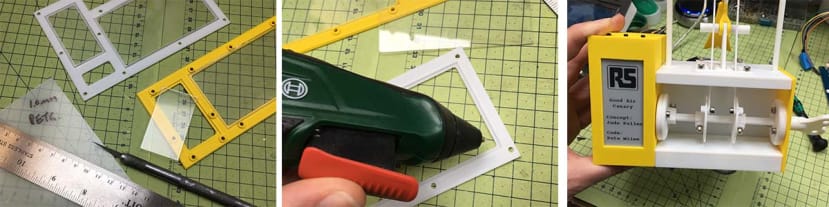
Part 1: Download 3D Files for Printing. See attachment ESDK 3DP

If you open Solid Works files, you will see the above assembly ‘GA’ (General Assembly), if you don’t have this, you still have all the individual STL parts for printing.
The Files can be found at LINK, and are free STLs.
Part 2: 3D Print STLs.
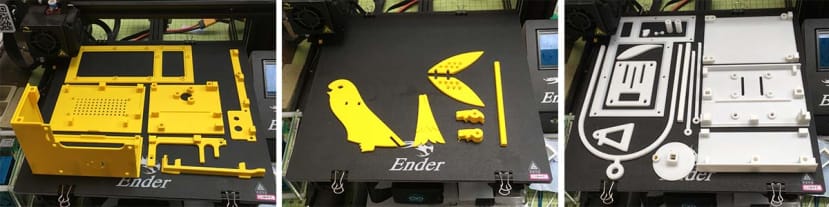
These are the layouts of the build plates on my Ender 3. The bed size is 235x235mm, so although you can cram a lot on, I would only do this if you are very confident of your printer’s settings. If new to this, print a bit at a time.
What you will note from all of the parts is that most have an ‘obvious’ flat surface - this is intended to sit on the ‘bed’ of the 3D Printer. Most parts have been designed to not need much (if any) build support, with the exception of the ‘Double Claw’ (foot of the Canary) which has no flat side - so does need build support.
You do not have to print in the two colours as shown - and in many ways, I’m excited to see what variations people create!
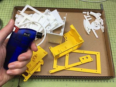
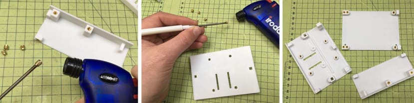
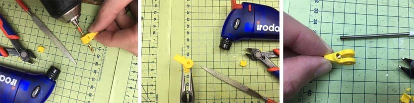
Part 3: Blowtorching / Finishing.
This part is optional, and should only be done if you feel confident in using a mini blowtorch. Safe to say it’ll burn you (and the part) if you linger. Be warned. The purpose is to singe off any stringing (cobweb like bits of PLA left after printing), and with practice, this is fast and easy to do.
Part 4: Finishing of 3D Printed Parts.
Much like decorating a house; good preparation often takes as long as the painting itself - but the results are always better, and last longer. Doing a good job in preparation will pay off later on, so I kindly recommend putting on a fun movie or some music, and just take your time with these steps at a leisurely pace. The rest of the build will then come together at rapid speed.
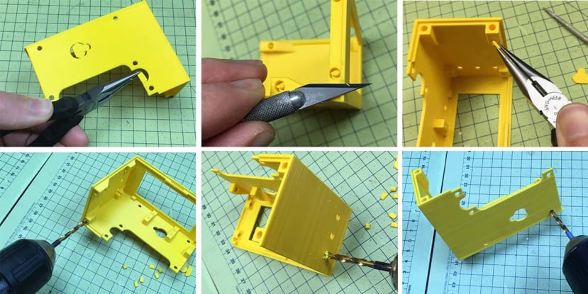
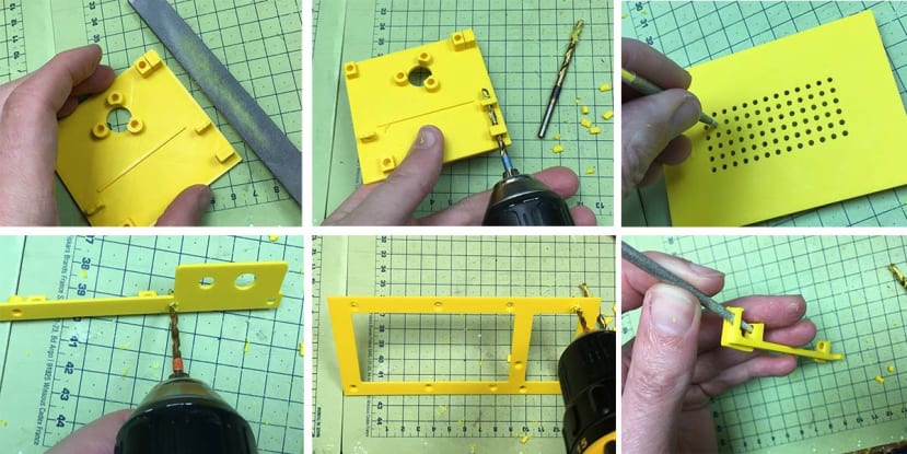
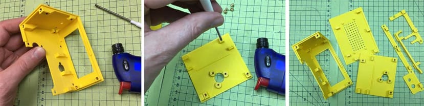
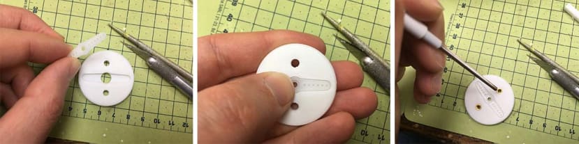
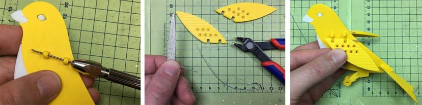
Use Drill, Knife and Pliers as shown to remove any build support, rough edges, and tidy up any small cosmetic build imperfections which often occur with many prints, even if optimized.
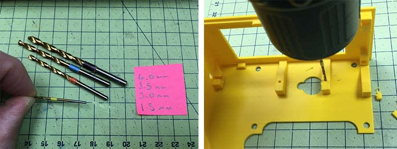
Note - I have colour coded the drill bits to help you, but also it helped me to not accidentally confuse one size with another. It is easily done, and care should be taken to only ‘reem’ the holes (ie make them nicely circular through removing only a little material - do not ‘drill out’ and make them larger).
The Servo Holes are the only exception where the hole will need some ‘proper drilling’ - enlarging with a 1.5mm bit, so as the Servo Screws fit just right. This is the only part of the build that uses ‘self tapping’ screws like this, as they come with the servo in most cases.
If you are interested - the reason for not simply ‘making the holes fit first time’ is that the holes produced by 3D Printing are always rather ragged, and not that strong/accurate. So it is actually better to design holes a little smaller (e.g. the holes which pass the screws are 3.2mm in CAD, but end up being about 2.8mm in raw prints, and hence enlarging to 3.0mm is necessary). I learned this from my time at Dyson, and it is a good skill to learn as your parts will also not split as there is too much force of the screw/thread pushing the printed layers apart.
The above images are showing some of the parts and how they were prepared, but the general approach can be done to all the parts - including of course the white PLA parts.
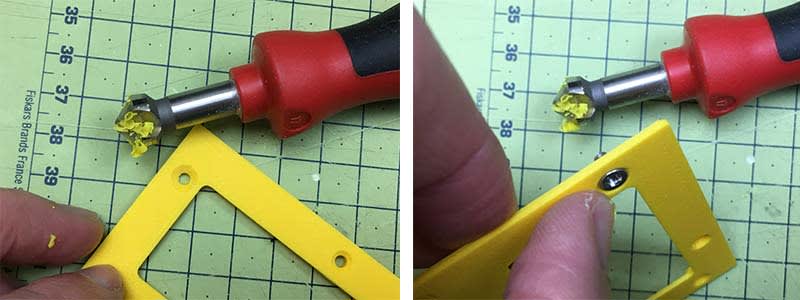
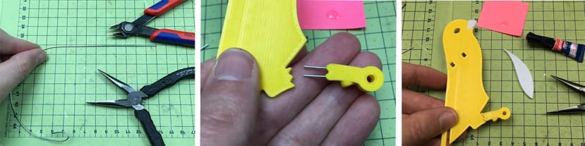
The Base Plate benefits from using a hand countersink tool to ‘smooth’ and enlarge the holes. If you do not have one of these (though common as a drill bit in most ‘fun pack’ style drill bit sets in DIY stores), you can do this by using a larger drill bit (like 8mm), and although the angle is more shallow, the overall effect of ensuring the screws fit nicely can be achieved. Just take care to do this with the piece flat on a table to avoid slipping - the bits are still sharp, and the piece can snap.
The White PLA Parts should now seem straightforward enough now. If unsure - which hole is which, start small and only enlarge if sure. It will become more apparent when you start adding Brass Inserts as to which are the larger 4.0mm holes, so if in doubt wait a few steps.
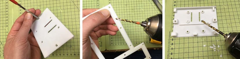
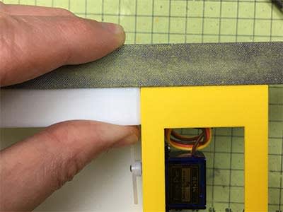
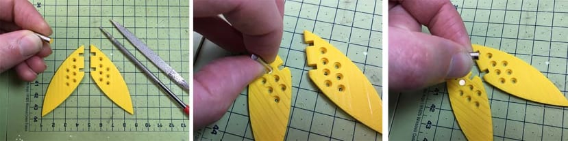
Shadow Gaps - these are a feature you see on any product not made by Apple (who uses statistical tolerancing to assemble each part to a corresponding part by its exact size). Most traditionally toleranced parts have to assume a degree of imperfection, and so designers/engineers realised that by emphasising the ‘gap’ - this actually made it ‘easier on the eye’. If you look at many plastic goods you will see a deliberate ‘gap’ - this looks better on the eye than if they tried to make it flush and failed. So we are doing the same here - as obviously 3D Printing is far less accurate than injection moulding!
Either way, even when your printer is doing a good job, you may still need to ‘tidy up’ the ‘L’-shaped gap, using a fine file as shown. The trick is to start with small, but firm pressure, and work up to longer, yet gentler strokes. If unsure - have a practice on a scrap of plastic first.
The final picture shows a closeup of how the plastic will come together and the idea is any slight gap is made less jarring to the eye by this ‘trick of the trade’. Try it on your models!
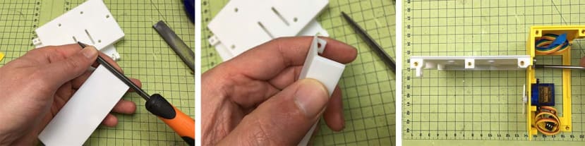
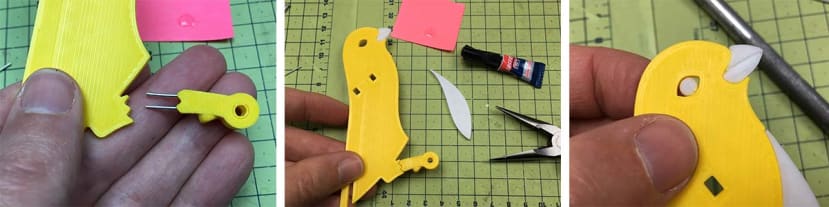
Part 5: Threaded Brass Insert - insertion technique.
I have documented in more detail how to insert Threaded Inserts into PLA in previous tutorials, and for the ESDK Kit, so please check these out if you need more guidance.
Anyone would think I have shares in Threaded Inserts, or am on commission from RS - but I am [sadly] not. But since I learned this technique at Dyson, I have not worked without it. Even though this could have been designed to work with 1-time-only ‘self-tapping’ screws, or indeed, I could have printed more intricate parts - consolidating many parts into one...but I personally feel this is not in keeping with the ethos of Open Source - and setting people up to be able to change out a single part (without reprinting the entire project). It is unlikely but not impossible you will spot a small mistake in this project - in which case you/I will only need to upgrade a single part. And this is of course why I try to avoid glue, as it is nearly impossible to undo.
The same applied to the Yellow pieces. You may note - I’m using a long threaded bar - this is a homemade handle of some plastic tube on an M3 threaded rod. The reason for this is part accuracy, but also conduction of heat takes longer to reach my fingers! If you don’t have this, simply use an M3 bolt with as much length as possible.
And you’re done with Preparation! Now the fun part can start...
.....................................................................................................................................................
Well done, you now need to jump off and go to the supporting article for the controller build, by Pete Milne.
See you back here soon.
.....................................................................................................................................................
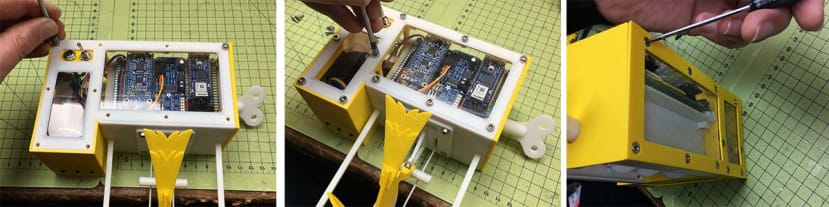
Section 2: Building the Circuit
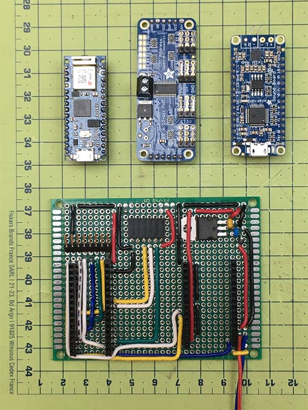
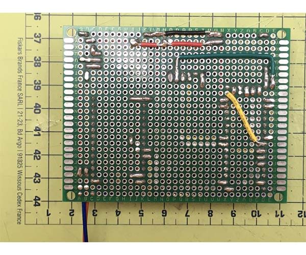
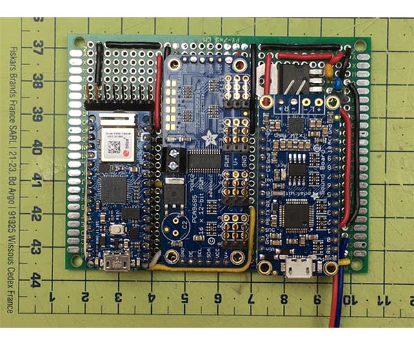
I’ve not done a ‘step by step’ of how to solder the wires, but rather have shown the end result I took from following the circuit diagram. There is no ‘one way’ to assemble your PCB, but I found that working on the careful positioning of the connectors was key - ie making space for the eINK screen wires to fit easily, etc.
You can of course solder the Mini PCBs (Arduino, etc.) directly and avoid using the header-pins, but I find this can be a problem if you make any mistakes.
Lastly, one small quirk I did with the Servo Board was to use right-angled header pins *underneath* the PCB, and then ‘slot’ these into the female header sockets. But given it is only 6 pins, I would suggest you can just solder it directly to the green PCB for simplicity.
With the 3D part preparation all done - you can now start fixing the electronic components! I suggest skim-reading this section first, as some of the assembly is dependent on a certain assembly sequence (e.g. you need to put the screen white pieces together before installing the screen).
Section 3 - Assembly Guide
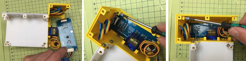
Part 1: Install Servo, Buttons, Screen & Speaker.
This is probably one of the most tightly packed parts of the project, so if it seems a bit tricky - rest assured, it’s mostly ‘downhill’ after this!
The reason for making this so compact was that it rather defines the other dimensions of the build - if there was much more ‘frame’ or bezel around the screen, this would make the other parts need to be bigger also, as the yellow part is half the width of the white part, etc.).
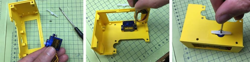
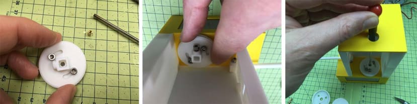
Most Servos are sold with the Screws and ‘Horns’ included. I’ve used a generic one ‘9g’ as they are often listed as, but the key advice is to take care screwing together the final screw in the horn, as it is easy to put in crooked and this will mess up your operation.
Install the PCB with just one screw as shown, (we add the second screw later). As this part is ‘DIY’ (cut to size by you), be aware you may need to file to fit. It’s worth getting right now (so the buttons press smoothly), rather than have to go back and fine-tune later.
These screws are important to fit before the Screen is fitted! Assemble the Top Plate first (as shown in prep - check that the Shadow Gap fits nicely between the two parts. File to fit if not). Then pre-assemble the Back Plate and Lower Shelf, then attach this as shown - with the two screws near to where the screen will go.
The step all comes down to how much of a perfectionist you are. The parts go together with pretty good tolerance, but if you want to get it perfect, I suggest lightly filing down any difference between the base of the two parts.
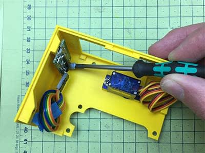
Slide the Screen into position, as shown. Lay it over the Screen Support, and screw it into the same boss that holds the PCB in place. (Again, check the buttons work nicely). I’ve shown the Speaker Wall in place here - just to show you how the screws go, (with the speaker out of the way for clarity), but of course, fit it with the speaker as shown.
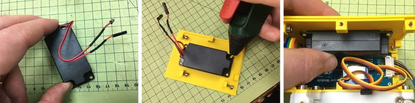
It is recommended that you shorten the length of the wires from the speaker - as this reduces the resistance, and gives a better sound. Do this as shown at a length of around 15cm. Although I found that my speaker ‘friction fits’ onto the studs if you want to you can add a tiny bit of hotmelt to hold in place. (In industry they often use what is called a ‘heat stake’ - which would melt the protruding yellow studs down over the speaker - like a rivet, but although you can do this, it’s a bit permanent for my liking!).
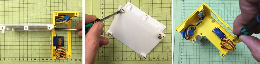
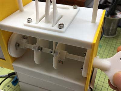
Part 2: Installing the PCB.
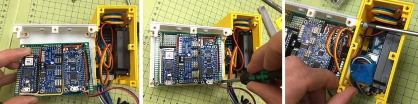
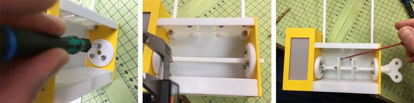
Install the PCB ‘Motherboard’ as shown. Take care not to over-tighten the PCB into place. Screw in the Cable Restraint as shown (unscrew the screws, then add back in place).
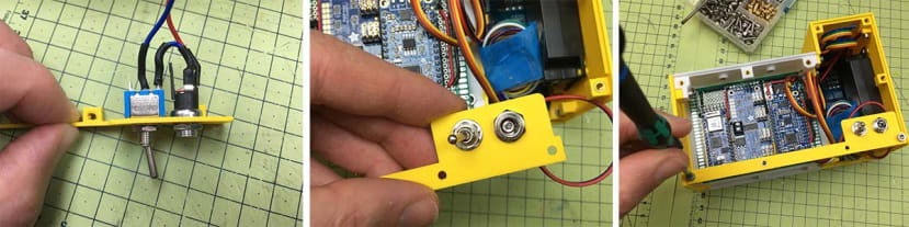
Wire up your Switch and Socket as shown.
Add the yellow Right Wall as shown. There is one annoyingly tight screw (middle image) that requires some fiddly manoeuvring of the ball-nose Hex Key to get into place. In all honesty, the assembly will cope without it, but it can be done with patience.
Plug in the Servo Lead as shown. Take care to observe orientation. Likewise part close attention to the wires of the eINK Display. Attach the Speaker Cables as shown.
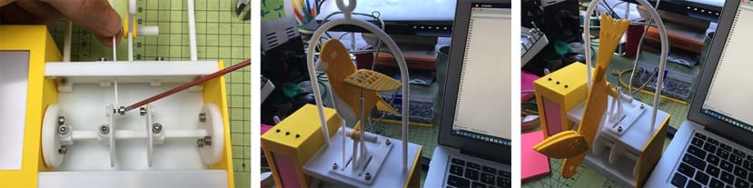
Part 3: Automata Wheels
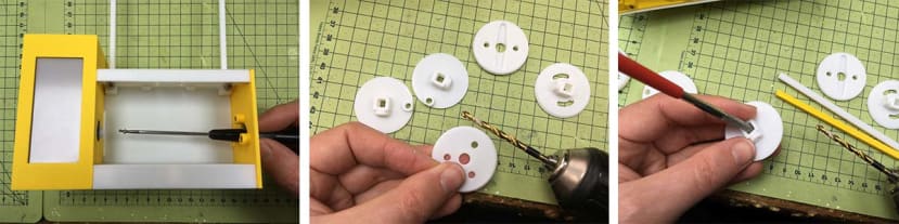
Unscrew the Horn from the Servo. Drill / File the discs to fit.
Take the Horn and press firmly into the Housing. You may need to file down the hole - but it is designed to be a snug fit, not loose, as this keeps it centred. Add Brass Inserts if you have not already done so.
This is a useful part as it allows you to fine-tune the angle of the wheels without needing to dismantle everything. Install at ‘full lock’ in one direction, and then install the full extent of the Servo in the full extent of its rotation. Screw the Horn Screw back into the Servo as shown.
Install the 3-hole Calibration Disc as shown. Slide in the Axel - and screw into place.
This is quite hard to explain in words, but the point of this Calibration Disc is to be able to move around in vertical and horizontal directions - this to take up any build/3D print errors over the length of the axel, and so you can get it perfectly straight from the servo-side to the other side. This will become more obvious when you start seeing the wings of the canary move, but I’ll be honest it’s more of the Engineering Nerds to get it ‘just so’ and I’m sure the Canary will work pretty well without it! But if you’re reading this far, you probably are that person - so enjoy the calibration!
Part 4: The Canary.
As you may have gathered by coming this far in the build (and if you’ve seen RadioGlobe) - I have a quirk of wanting to hide all screws as much as possible - with the exception of ‘user serviceable/adjustable’ screws. As all 3D Printers differ slightly and accounting for differences in human building skills, the Canary and Automata Mechanism are exactly the sorts of things that you will need to tweak and get working ‘just right’. For those of your who are not looking to just complete a jigsaw or ‘paint-by-numbers’ style project, this is where it gets fun: Each of these elements allows you to interchange the aesthetics (you can switch out the wings, print colours, adjust movements in code), and give the project your own flourish. Perhaps you might even put an entirely different Automata creation on top of the IoT base unit.
So please consider the following steps the ‘default’ - and enjoy making them your own.
Drill out the centre-hole of the Canary Foot, and carefully remove the build support. Lastly, insert the Brass Insert as shown.
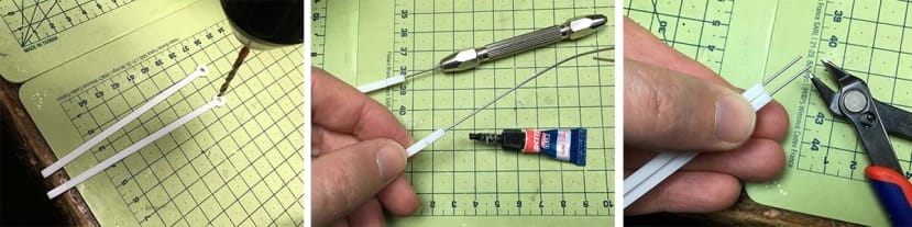
Take some 1.0mm Stainless Steel Wire (or Large Paperclip Wire will do fine also), straighten out, and cut two short lengths around 30mm long, and superglue one side into each hole as shown. If you need to clean out the holes with a 1.0mm drill bit (shown in a Pin Vice) I recommend doing this, as it means you can fit it with less effort. Once you have everything set up, you can then trim the wires and fit them into the body of the Canary.
With the feet added, you can now add the Beak, Breast and Eyes as shown. I strongly suggest checking the fit first, and using a scalpel and file to get the fit just right, as these are some of the most visible parts of the build - so are worth getting right.
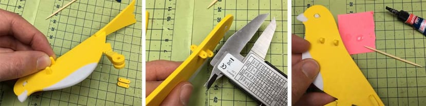
The 13mm Wing Pings are a deliberately tight fit into the Canary Body. This is because they are prone to effort if free to move. Firmly press them in (against a clean surface/object), and use the back of a set of Calipers to check they are protruding equal distances at all 4 points. Once you have this, using a minimal amount of Super Glue, fix it in place.
Using a 1.0mm drill bit drill through the holes as shown, and ‘wiggle around’ to make the holes slightly larger than the drill bit, so it runs smooth. Next (like the Feet) but 2x 30mm sections of straight wire. If it’s not straight, use pliers to ensure it’s as straight as you can get it. File the tips, and insert as shown.
File off any defects in the smallest holes of the wing’s 7 holes. Insert one of the Magnets 4mm (dia) x 1mm (thick) magnets into the top level of the hole shown. Then *flip* the stack of magnets over (to reverse the polarity), and insert the second in the corresponding mirror location. (The wings should now ‘attract’ each other.
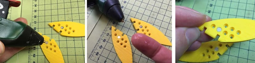
The magnets should stay in place with friction (i.e. tight fit)... if not, add a tiny bit of Hot Melt as shown. (Hot melt still allows you to move the magnets if you wish later). Take care not to burn yourself, but a pro tip is to use saliva-on-your-finger to press the bead of glue down to smooth out and fill any gaps. Do not do this with large volumes of glue, as this only works if the thermal mass of the glue is tiny, relative to the saliva on your finger. (Or wear lab gloves if you have sensitive skin, or are worried).

To create the stand, glue as shown - taking care to ensure the protruding ‘foot rest’ faces backwards. Use some paper (or a set square) to check it is perpendicular - get this right, otherwise, your Canary will not roost straight!
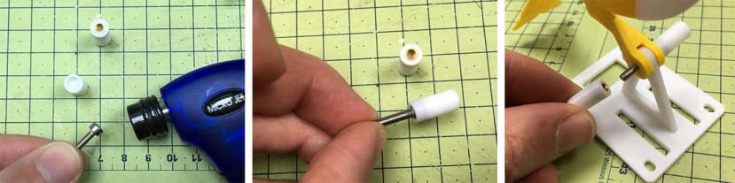
To make the ‘Perch’, (which is essentially fake, but allows the canary to have a rotational axis to pivot), heat up the head of an M3x16 Hex Bolt - and insert as shown. Add the Brass Insert to the corresponding perch with the smaller hole. These should then thread through the assembly. If the motion is sticky, file down, and add a tiny bit of pencil lead inside (graphite is a lubricant), and if too slack, add a fine layer of Super Glue - let dry - then file down again to get a close fit, that still moves freely.
Part 5: Connection of Canary to Base Unit.
Drill Out the holes in the Arms as shown - with a 3.0mm bit. Do this very slowly and with minimal pressure so as not to shatter them. If in doubt - use the circular file. Insert 1.0mm wire (or paper clip) as shown - and strim to around 15-16mm protruding from the end of the 3D printed material. It is better to have ‘too long’ and trim back, than too short.
Screw the Arm in place as shown - allowing it to move freely. The brass insert should probably hold the bolt in place, but if too loose add some PTFE tape, Hot Melt or threadlock if you like - to keep it in place. Next, fit the tip of the wire into the hole under the Magnet. When you rotate the wheels below (manually using the key or using the code) it should tip forward and then fall from the perch - as the Arms ‘break free’ from the Magnet’s hold. Move the Arms back into the starting position to re-attach the wings.
Part 6: Starting Servo Position
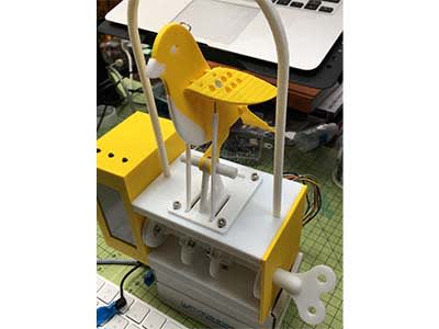
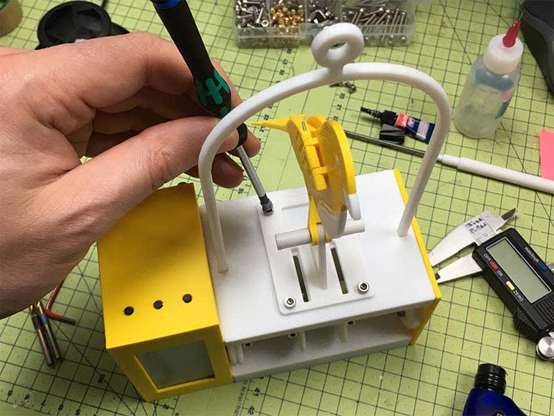
You should now have something looking like this. Below is a close up of the Automata ‘Discs’. Use the Key to turn *gently* the Servo anticlockwise, so that it stops. This is your starting position.
This close-up shows how I have set things up, ready for the unit to be powered up:
- The Servo Mounting Disk - is slightly off from ‘full lock’ by about 40 degrees.
- The Two Main Wheels are spaced such that the Arms move freely.
The Two Main Wheels are set such that the screw bosses are 180 degrees from the Servo screw boss. - The Bolts holding the Arms are positioned at about ‘10 O’Clock’ should you look from the side with the Key.
This is pretty close to the ideal starting position, but turn the key Clockwise 180 degree to see if the canary goes through flapping to falling to ‘disconnecting’ the Arms so it is fully ‘dead’. If this all works, the code should work pretty close the first time.
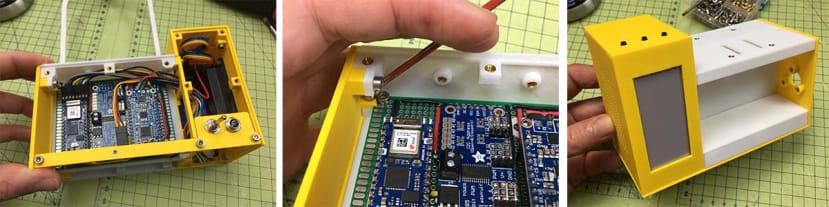
It is at this point you may wish to stop with the build, and skip to the code part. The reason being is that you still need to access the Arduino and FX Soundboards - using their Micro USB Connections - and to do this, you need the Base and possibly Back panels removed. However, if you’re ok with simply removing these again later, then press-on and finish the build...
Part 7: Back Plate & Base Plate.
Having checked the fit of the Back and Base Plates (file to fit if tight), and checked fit with screws - you are now ready to cut small sections of PETG (1.0mm thick) or other transparent plastic - and tack in place with Hot Melt Glue. If you want to make this much stronger, I suggest sticking in with Epoxy - not Super Glue, as this tends to ‘boom’ (frost white).
I suggest placing the assembly over the edge of the table as shown - this is to ensure the Canary is not bent out of shape when working on screwing the Back Plate in. You may notice you need to remove the two screws shown, and then reinsert them. Continue adding screws to secure both plates - Hex M3x6mm for the back, and CSK (countersunk) M3x6mm for the base.
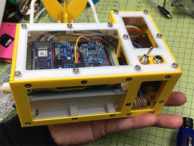
Like the RadioGlobe project - you should have a nice visual side, with a clean aesthetic - but that can be rotated to show off a cool ‘pop-the-bonnet’ style internal view of all the IoT electronics.
You are now ready to upload the Code if you have not done so already. Yep - you need to remove the Back and Base sadly...I had contemplated putting a small slot in the bottom, but as this model needs to be kids-proof for my home, (and for RS who will likely have it at a trade show or such like, I declined to do this), as you’re unlikely to be regularly updating the software (I hope!). However, the files are all open source, so feel free to contribute an upgrade!
Section 4: Canary Calibration.
Part 1: Servo - Code Calibration
Now that you have the Canary code uploaded and working more-or-less correctly, you may want to ‘fine tune’ the motions, and the following gives a few suggestions of basic code calibration...
Servo Position Adjustment.
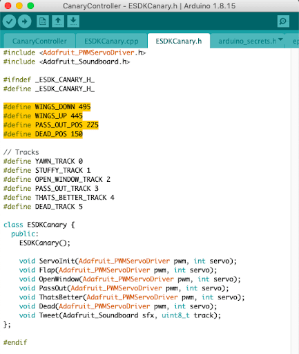
If you look at the ESDKCanary.h file within the CanaryController.ino file in Arduino, you’ll see a section as follows...(highlighted in yellow here). These are the fundamental positions of the main movements of the Canary, and correspond to servo positions.
I found that my Servo motor moves from 0-180 degrees (slightly 200 if you want to be exact), and that this corresponds to a Servo signal of 500-100 in the code. However, if you have worked with Servos before you know that they do not like being held at the absolute extent of their range (ance why there is 200 degrees for a ‘180 degree servo’.
Because of this, I adjusted my starting position to be 495, rather than 500. Likewise, the end or ‘death’ position I found was fine at 150, rather than 100, so I ‘backed it off’ to avoid the servo straining unnecessarily.
In addition the Wing’s apex (high point) - listed as WINGS_UP, I found was 450, but aesthetically it just looked better at 445, so I changed it.
The PASS_OUT_POS was adequate at 225, but you may find your needs to be 220 or 230 - and these are easy edits to make to the code without needing much prior knowledge of Servos or the code to work with them.
Flapping Style
If you want to get more into the ‘character’ of the Canary’s movements - you can adjust the corresponding ESDKCanary.cpp file - where you can cut and paste ‘units’ of the code, that create the flaps via calling the WINGS_UP and WINGS_DOWN movements. You could for example make the canary flap more times by repeating certain sections, or speed it up / down - by changing the delay (shown in yellow, below)...these are all infinitely configurable and will make more sense as you change a parameter and see what the Canary does in response.
Part 2: A Note on Death and Reincarnation (or Home vs Public Use).
The default code is written such that when the CO2 reaches 4000ppm - the Servo rotates its full travel, the magnets force is overcome, and the Canary ‘dies’. This ends the programme (with a tombstone) and in my opinion warrants the ‘effort’ of being tasked with manually resetting the bird back into position, and to restart the programme by pressing the middle button.
I believe that if you’ve been working in 4000ppm, you should go through a slightly arduous task to remind you to take this seriously and crack a window. There is a bit of ‘shaming’ going on here: if I let my canary die, my 5-year-old Son would be slightly ‘disappointed’ that I let it ‘die’, as I was breaking the rules, and my wife would likely tell me off for working in a bad way (and being a hypocrite having authored this project in the first place).
However, if this is too macabre, or you perhaps have a good reason why you don’t want to be disturbed while working at 4000ppm CO2 (Perhaps you want this in a public space like a School, Museum or such like - where resetting is not practical), you can adjust the code to move the servo only go as far as the 3000ppm setting, which is reversible, and the Canary ‘reincarnates’ by returning to the upright position - with a ‘Phew - that’s better’.
Comments