MQTT: Part 4 – Industrial Controller
Follow article
 Dave from DesignSpark
How do you feel about this article? Help us to provide better content for you.
Dave from DesignSpark
Thank you! Your feedback has been received.
Dave from DesignSpark
There was a problem submitting your feedback, please try again later.
Dave from DesignSpark
What do you think of this article?
MQTT series covering development of networks on ROCK SBC’s and Arduino Portenta Machine Control with VSCode, Arduino CLI and Python
This fourth article in the series looks at how the Arduino Portenta Machine Control (PMC) can be integrated into our IIoT network infrastructure.
We use the Linux Development Host built in Part 1 to write test and example code in VSCode and flash it to the PMC using the Arduino CLI.
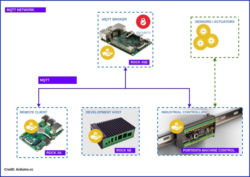
The PMC contains an embedded Arduino Portenta H7 module with a dual-core MCU so we show how to divide up an IIoT application that samples thermocouples and controls the on-board I/O whilst publishing the readings to the MQTT broker developed in Part 3.
By the end of the series, you should have a working IIoT network that looks something like the diagram above for use in Industrial Control, Building HVAC, Smart Agriculture or even controlling your own micro-brewery!
Parts List
- Arduino Portenta Machine Control (222-6773)
- 24VDC / 4A Power Supply (190-4203)
- USB-C Power Cable (266-2599)
- Thermocouple Type J (015-0004) , 2x Thermocouple Type K (015-1192)
- 6x Bootlace Ferrule (178-7282) , Crimping Tool (701-0565)
- 24VDC Green LED (610-2691) , 24VDC Red LED (017-7529)
Thermocouples
The PMC has hardware support for J & K type thermocouples connected to the onboard Maxim MAX31855 Cold-Junction Compensated Thermocouple-to-Digital Converter.
Each thermocouple has 2 leads, a positive and negative terminal which are connected to the positive TPn and negative TNn connections on the Temp Probe block of the PMC.
Here’s the connection details for the probes used:
T/C Conductors Length +Positive -Negative Allied RS order
‘K’ 1/0.3mm 2 metres Brown Blue 70636357 (015-1192)
‘J’ 1/0.3mm 2 metres Yellow Blue 70636353 (015-0004)
Crimp bootlace ferrules onto the thermocouple leads and insert them into the correct sockets on the PMC Temp Probe connector block. The K type probes are in TP0 / TN0 and TP1 / TN1 and the J type is connected toTP2 / TN2. Notice that there is an empty connection for RTD probes between each pair of connections.

Firmware
You can download all the firmware examples to flash onto the PMC from the DesignSpark GitHub onto your Linux Dev Host that we built in Part 1
$ git clone https://github.com/DesignSparkRS/pmc-thermo.gitYou will also need the MQTT broker that we built. All the details are in Part 3
Thermocouple Test
The Arduino_MachineControl library has software support for reading J & K type thermocouples and there’s an example program provided but it has a couple of errors in it.
To test the thermocouples, connect a USB cable from the PMC to the Dev Host. This can also be used to power the PMC for this test.
Now open the pmc_thermo_test directory in VSCode and load pmc_thermo_test.ino.
This tests that the probes are working as expected by sampling each one in turn and outputting the readings to the serial UART.
The probes are setup and initialised in setup() and each probe is read by sample_thermocouple() where the channel and probe type are passed as arguments.
The original Arduino example code is here but the probe arguments are missing. The probe library is in Arduino_MachineControl/src/utility/THERMOCOUPLE/ directory if you are curious about how it works.
pmc_thermo_test.ino
#include <Arduino_MachineControl.h>
using namespace machinecontrol;

void setup() {
  Serial.begin(9600);
  temp_probes.tc.begin();
  temp_probes.enableTC();
  Serial.println("Thermocouples enabled");
}

void sample_thermocouple(int channel, int t_couple) {
  temp_probes.selectChannel(channel);
  float degrees = temp_probes.tc.readTemperature(t_couple);
  Serial.print("Temperature CH");
  Serial.print(channel);
  Serial.print(" [°C]: ");
  Serial.println(degrees);
}

void loop() {
  sample_thermocouple(0, PROBE_K);
  sample_thermocouple(1, PROBE_K);
  sample_thermocouple(2, PROBE_J);
  Serial.println();
}
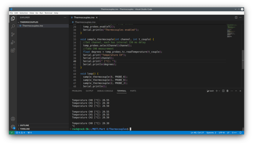
Open the VSCode Terminal to compile and upload the program, then run the CLI Monitor to see the output of the thermocouple readings:
$ arduino-cli compile --fqbn arduino:mbed_portenta:envie_m7
$ arduino-cli upload -p /dev/ttyACM0 --fqbn arduino:mbed_portenta:envie_m7
$ arduino-cli monitor -p /dev/ttyACM0
Connected to /dev/ttyACM0! Press CTRL-C to exit.
…
Temperature CH0 [°C]: 20.55
Temperature CH1 [°C]: 20.30
Temperature CH2 [°C]: 20.52
Readings are very fast and accurate to +/- 1 degree celsius
MQTT Test
This next test ensures that the PMC can connect to the MQTT broker on the local network and publish data out and receive data in, over MQTT.
Connect up an Ethernet cable to the Ethernet jack on the PMC for this test.
The PMC will be connected to the MQTT broker that we built in Part 3, making sure it is configured to accept anonymous connections on port 1883.
Once a connection to the broker is established the PMC will publish a test message then subscribe to incoming commands that will control the LED on Digital I/O channel 00 on the boards Digital Output section.
Open the pmc_mqtt_test directory in VSCode and load pmc_mqtt_test.ino. If necessary, update the IP addresses to match your network settings:
pmc_mqtt_test.ino
#include <SPI.h>
#include <Ethernet.h>
#include <PubSubClient.h>
#include <Arduino_MachineControl.h>
using namespace machinecontrol;

#define CH00 0
byte mac[] = { 0xDE, 0xED, 0xBA, 0xFE, 0xFE, 0xED };
IPAddress ip(192, 168, 1, 61);  // PMC IP
IPAddress server(192, 168, 1, 60);  // Broker IP

void callback(char* topic, byte* payload, unsigned int length) {
  String buffer = "";
  for (int i = 0; i < length; i++) {
    buffer += (char)payload[i];
  }

  if (buffer.length() > 0) {
    if (buffer == "OFF")
      digital_outputs.set(CH00, LOW);
    else if (buffer == "ON")
      digital_outputs.set(CH00, HIGH);
  }
}

EthernetClient ethClient;
PubSubClient client(server, 1883, callback, ethClient);

void setup() {
  Ethernet.begin(mac, ip);
  digital_outputs.setLatch();

  if (client.connect("arduinoClient")) {
    client.publish("test/out", "hello world");
    client.subscribe("test/in");
  }
}

void loop() {
  client.loop();
}
Compile and upload the code from the VSCode Terminal with:
$ arduino-cli compile --fqbn arduino:mbed_portenta:envie_m7
$ arduino-cli upload -p /dev/ttyACM0 --fqbn arduino:mbed_portenta:envie_m7
Now open a separate serial Konsole in KDE and subscribe to the broker on topic test/#
$ mosquitto_sub -h rock-4se -t test/#In the VSCode Terminal send ON and OFF messages over MQTT:
$ mosquitto_pub -h rock-4se -t 'test/in' -m 'ON'
$ mosquitto_pub -h rock-4se -t 'test/in' -m 'OFF'
The Hello World message should be published in the subscriber Konsole and you should be able to control the LED on channel 00 by sending ON and OFF commands in the VSCode Terminal:

Dual Core
Inside the PMC is a Portenta M7 module with an STM32H747XI dual Cortex®-M7+M4 32bit low power Arm® MCU.
We will divide up the next program so that the lower-powered M4 core is used to sample the thermocouples and the more powerful M7 core will be responsible for managing the network connection and MQTT messaging.
Connect up a couple of 24V LEDs to the I/O ports to simulate a real control scenario and hook up the 24V power supply.

M4 Core
Open the pm_thermo directory in VSCode and load up pmc_thermo_m4.ino which will run on the M4 core.
The code continuously samples each thermocouple probe using the helper function sample_thermocouple() and passes the readings to the M7 core with an RPC call in callCopyTemperatureFromM4().
It also blinks one of the I/O channels in a separate thread because we love blinking LEDs. You will notice that this is unaffected by anything else which is going on on both cores.
pmc_thermo_m4.ino
#include "Arduino.h"
#include "RPC.h"
#include <Arduino_MachineControl.h>
using namespace machinecontrol;
using namespace rtos;

#define TCH0 0
#define TCH1 1
#define TCH2 2
#define IOCH00 0

Thread copyTemperatureThread;

float sample_thermocouple(int channel, int t_couple) {
    temp_probes.selectChannel(channel);
    return temp_probes.tc.readTemperature(t_couple);
}

void callCopyTemperatureFromM4() {
  while (1) {
    delay(1000);  // Wait for next calculation
    float temp_ch0 = sample_thermocouple(TCH0, PROBE_K);
    float temp_ch1 = sample_thermocouple(TCH1, PROBE_K);
    float temp_ch2 = sample_thermocouple(TCH2, PROBE_J);
    auto result = RPC.call("copyTemperature", temp_ch0, temp_ch1, temp_ch2).as<float>();
  }
}

void blink_led(int io_channel) {
  digital_outputs.set(io_channel, HIGH);
  delay(1000);
  digital_outputs.set(io_channel, LOW);
  delay(1000);
}

void setup() {
  RPC.begin();
  digital_outputs.setLatch();
  temp_probes.tc.begin();
  temp_probes.enableTC();
  copyTemperatureThread.start(callCopyTemperatureFromM4);
}

void loop() {
  blink_led(IOCH00);
}
To flash it to the M4 core, open the VSCode Terminal and execute the following commands, passing the core_target as a string in the --board-options argument:
$ arduino-cli compile --fqbn arduino:mbed_portenta:envie_m7 --board-options "target_core=cm4"
$ arduino-cli upload -p /dev/ttyACM0 --fqbn arduino:mbed_portenta:envie_m7 --board-options "target_core=cm4"
When the PMC resets, not a lot should happen at this point as the M4 core doesn’t run by default. It needs to be started in the M7 code.

M7 Core
Now open a second instance of VSCode and load up the pmc_thermo_m7.ino code which will run on the main M7 core.
This is responsible for starting up the M4 core, connecting to the MQTT broker, publishing the readings sampled by the M4 core and performing simple logic to switch the I/O when the probes exceed a set temperature.
Temperature readings are passed from the M4 to M7 core by the RPC call in the M4 code. This triggers the RPC callbackcopyTemperatureOnM7() on the M7. The callback is mapped by the bind function in the setup(); RPC.bind("copyTemperature", copyTemperatureOnM7); and the values are passed as floats.
RPC.begin() creates the RPC instance and also boots the M4 core as a result.
The Ethernet connection is defined at the top of the file where the IP addresses of the PMC and MQTT broker are assigned. These need to match addresses on your network and the broker connection is formed during setup() along with initialising the I/O controller.
When copyTemperatureOnM7() runs, it copies the readings into global variables, prints the values to the UART and publishes a message containing the readings to the broker on topic test/thermos. The function must return a value so that the loop on the M4 can continue, otherwise, it blocks the thread. The frequency with which it runs is controlled by the M4 process. It also runs in its own separate thread.
The main() function runs the MQTT client.loop() which keeps the connection alive before running process_readings() which performs some simple logic to control the I/O channel connected to the red LED. This turns on if any of the probes go above the threshold temperature.
pmc_thermo_m7.ino
#include "Arduino.h"
#include "RPC.h"
#include <SPI.h>
#include <Ethernet.h>
#include <PubSubClient.h>
#include <Arduino_MachineControl.h>
using namespace machinecontrol;
using namespace rtos;

#define IOCH01 1
#define TRIP 25.0f  // Temperature threshold
float T1, T2, T3;
byte mac[] = { 0xDE, 0xED, 0xBA, 0xFE, 0xFE, 0xED };
IPAddress ip(192, 168, 1, 61);  // PMC IP
IPAddress server(192, 168, 1, 60);  // Broker IP
EthernetClient ethClient;
PubSubClient client(server, 1883, ethClient);

float copyTemperatureOnM7(float temp_ch0, float temp_ch1, float temp_ch2) {
  T1 = temp_ch0;
  T2 = temp_ch1;
  T3 = temp_ch2;
  Serial.println("M7: TemperatureOnM7 T1 " + String(T1) + " T2 " + String(T2) + " T3 " + String(T3));
  client.publish("test/thermos", ("PMC0," + String(T1) + "," + String(T2) + "," + String(T3)).c_str());
  return 1;  // Note: must return a value!
}

void process_readings() {
  if ((T1 > TRIP) || (T2 > TRIP) || (T3 > TRIP)) {
    digital_outputs.set(IOCH01, HIGH);
  } else {
    digital_outputs.set(IOCH01, LOW);
  }
}

void setup() {
  RPC.begin();  // Init RPC, also boots M4 core
  Serial.begin(115200);
  RPC.bind("copyTemperature", copyTemperatureOnM7);
  Ethernet.begin(mac, ip);
  digital_outputs.setLatch();
  digital_outputs.set(IOCH01, LOW);
  client.connect("pmcClient0");
}

void loop() {
  client.loop();
  process_readings();
}
Compile and upload to the M7 core. This time there’s no need to specify the core as the M7 is the default:
$ arduino-cli compile --fqbn arduino:mbed_portenta:envie_m7
$ arduino-cli upload -p /dev/ttyACM0 --fqbn arduino:mbed_portenta:envie_m7
As soon as the code has loaded the PMC will reset and the M4 core will blink the green LED at 1-second intervals and start sampling the thermocouples.
You can see the temperature readings being sent to the M7 core by opening the serial monitor in the VSCode Terminal:
$ arduino-cli monitor -p /dev/ttyACM0If you open a Konsole on the KDE desktop and subscribe to the broker on test/thermos you will see the readings being published by the M7 core process:
$ mosquitto_sub -h rock-4se -t test/thermosTouch any of the thermocouples and the red LED will turn on when the temperature rises above the threshold and it will turn off again as it cools below it.

Summary
The Arduino Portenta Machine Control is a powerful and flexible industrial control device with IIoT capabilities. In this article, we demonstrated how to connect industrial thermocouple probes to its onboard temperature sampling hardware and how to use the temperature readings to control the on-board 24V I/O.
We showed how to run the temperature monitoring task on the built-in Portenta’s M4 core and how to pass the sampled values to the M7 core. The M7 core was also responsible for connecting to an MQTT broker via Ethernet publishing the readings so that other clients on the local area network could access them.
This is how you can turn on your beer cooler in your brewing process or open the vents and turn on the fans in a smart greenhouse or HVAC system or whatever automation process you can think of.
References
DesignSpark GitHub: https://github.com/DesignSparkRS/pmc-thermo
Arduino Portenta Machine Control Product Documentation:
https://docs.arduino.cc/hardware/portenta-machine-control
Arduino Portenta Machine Control Thermocouple example:
Arduino CLI reference: https://arduino.github.io/arduino-cli/dev/
Comments