First steps to Direct Modelling Part 5: Look at the Combine Tool
Follow tutorial
 Dave from DesignSpark
How do you feel about this tutorial? Help us to provide better content for you.
Dave from DesignSpark
Thank you! Your feedback has been received.
Dave from DesignSpark
There was a problem submitting your feedback, please try again later.
Dave from DesignSpark
What do you think of this tutorial?
This tutorial requires:
DesignSpark Mechanical V6.0This tutorial is in progressive sections and will guide you with the main model creation commands in DesignSpark Mechanical. The first two sections will help you build two models (using the Sketch, Select and Pull tools) and the third section will show you how to assemble the models together (using a range of Move functions). Following sections will illustrate further skills, including Fill (removing features) and Combine (cutting into one model using another model or merging two models together). You will then be able to design your own parts and assemble them using the same tools and functions.
SECTION 5 - COMBINE TOOL
The combine tool is designed to allow two main actions to be carried out:
1. Using the shape of one solid to cut into another one, and
2. Merging adjacent or overlapping models into one object
The following exercise will go through some examples so that the skills can be applied to future work.
1. Open DesignSpark Mechanical (and close the welcome help screen)
2. Open the COMBINE MODELS file attached.
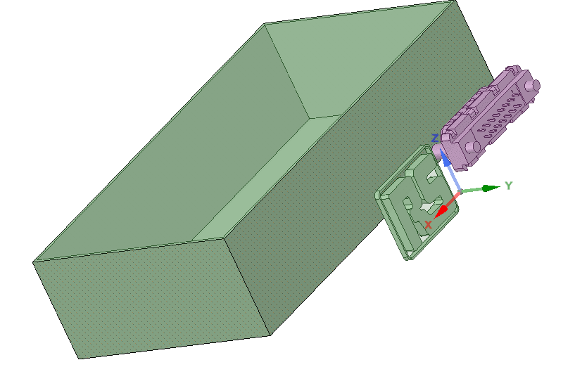
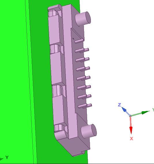
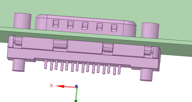
3. Triple left click on the connector to select it and press z to zoom in to the extents of the selected item
4. Select the Move tool on the Ribbon bar
5. Click on the anchor button to the left of the design screen
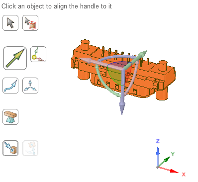
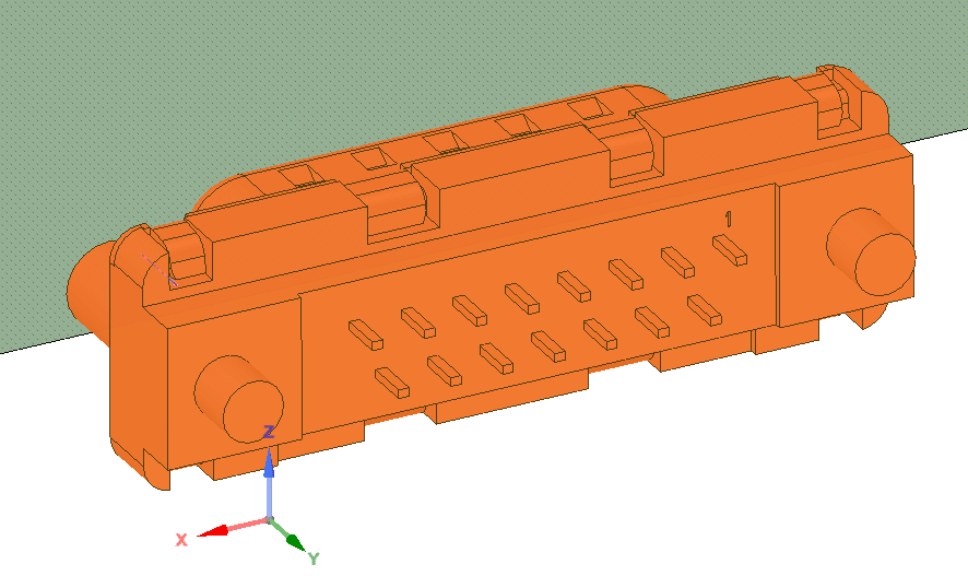
6. Select the inner face of the connector body by left clicking to place the move anchor on that face
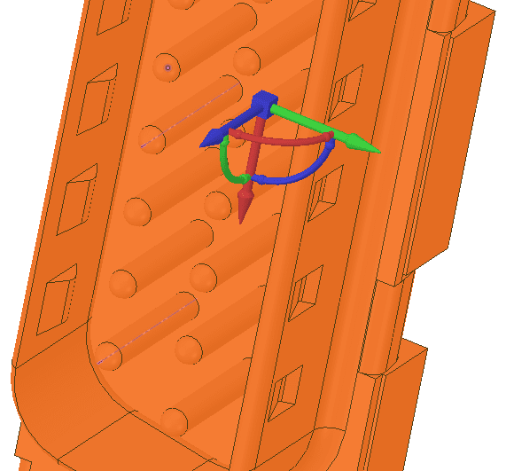
7. Left click on the blue arrow of the move anchor and then click on the “Up to” command icon
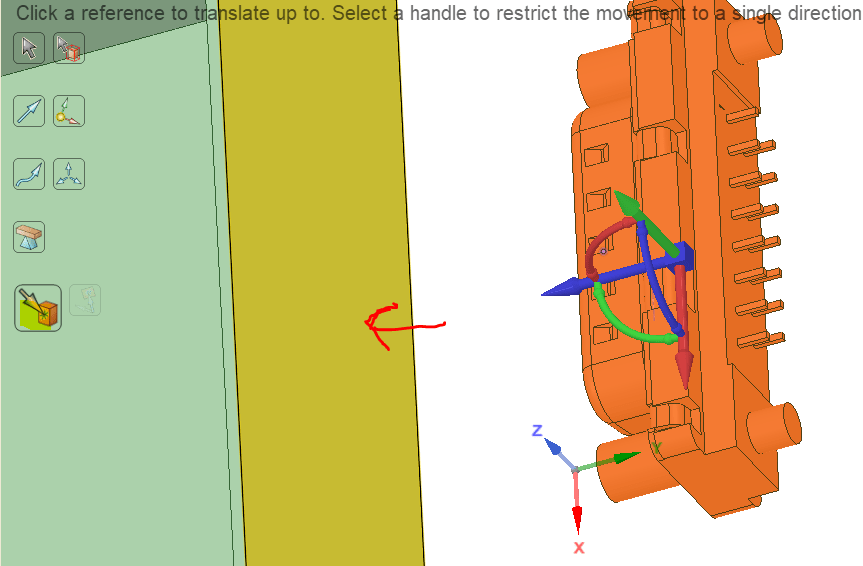
8. Select the outer face of the rectangular casing by clicking on it to move the face of the connector onto it
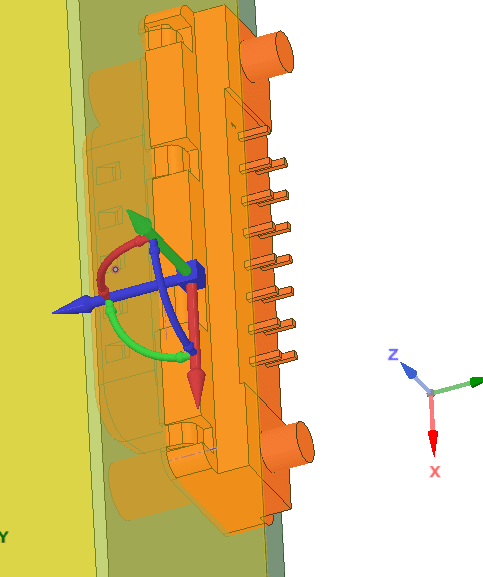
9. Click in white space to end the Move action
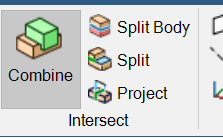
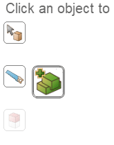
10. Select Combine on the Ribbon bar
11. As prompted, select the casing as the target object
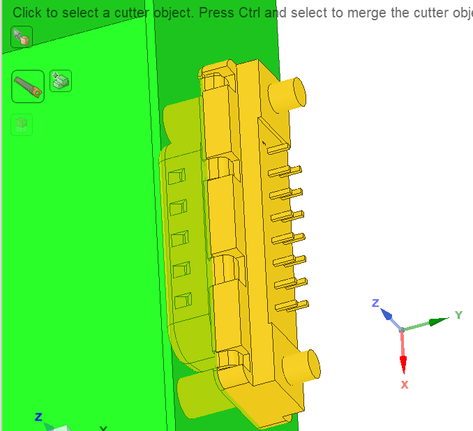
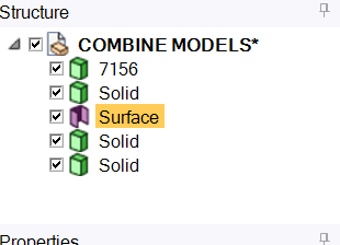
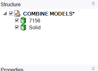
12. Select the connector as the cutter object (note that there are now lots of new solids listed in the structure tree – these are all the parts of the casing sidewall which have been cut by the profile of the connector)
13. Next to the 7156 connector solid in the structure tree un-tick the box to hide the object
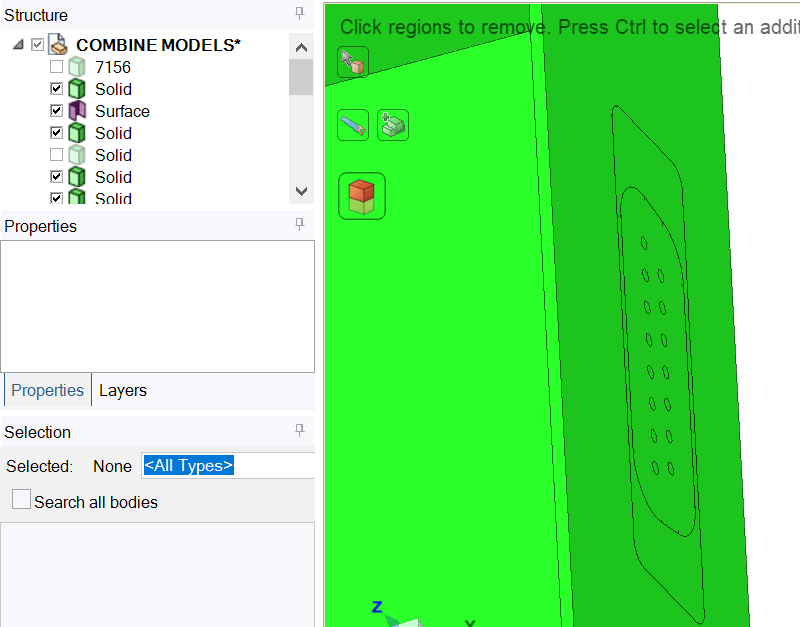
14. Whilst still in Combine mode, drag a select box around the lines in the wall of the casing created by the connector to remove those parts of the wall of the casing
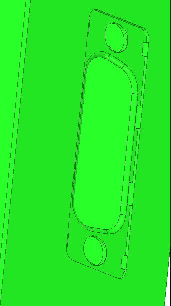
15. Click in white space to end the Combine action (note that the structure tree shows only the 3 solids again after all the cut parts of the casing have been removed)
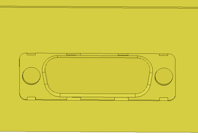
16. Re-tick the 7156 box in the structure tree to see the connector in position
17. Now position the RS logo using the Move and Move – up to tools so that it is placed onto the outer face of the casing as shown and note that there are now 4 solids shown on the structure tree (7156 connector plus the casing and the 2 parts of the logo)
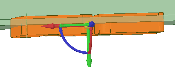
18. Click in white space to end the Move
19. Re-select the Combine tool on the Ribbon bar
20. As prompted, select the casing as the target object
21. Now, instead of selecting a cutter object, select the Merge icon as shown
22. Drag a select box around the RS Logo to select both solids and click on the logo
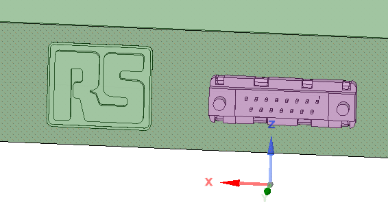
Note that the structure tree is now only showing 2 solids (the connector and the casing which now incorporates the logo)
The combine exercise is now complete. You may want to save these examples or continue to develop them.
Additional reading
First steps to Direct Modelling Part 1: Look at the Sketch, Select and Pull tools
First steps to Direct Modelling Part 2: Look at the Sketch, Select and Pull tools
First steps to Direct Modelling Part 3: Look at the Move tool
First steps to Direct Modelling Part 4: Look at the Fill Tool
First steps to Direct Modelling Part 5: Look at the Combine Tool