First steps to Direct Modelling Part 4: Look at the Fill Tool
Follow tutorial
 Dave from DesignSpark
How do you feel about this tutorial? Help us to provide better content for you.
Dave from DesignSpark
Thank you! Your feedback has been received.
Dave from DesignSpark
There was a problem submitting your feedback, please try again later.
Dave from DesignSpark
What do you think of this tutorial?
This tutorial requires:
DesignSpark Mechanical V6.0This tutorial is in progressive sections and will guide you with the main model creation commands in DesignSpark Mechanical. Part 1 and Part 2 will help you build two models (using the Sketch, Select and Pull tools) and Part 3 will show you how to assemble the models together (using a range of Move functions). Following sections will illustrate further skills, including Fill (removing features) and Combine (cutting into one model using another model or merging two models together). You will then be able to design your own parts and assemble them using the same tools and functions.
The models created in sections 1 & 2 are used in later tutorials. If you have not completed section 1 and 2 but need to work on later sections these are attached to the tutorial
SECTION 4: FILL TOOL
The Fill tool is designed to remove features from models and replace them with surrounding geometry.
In many cases it is clear and obvious how to do this but, in some cases, care is needed to ensure it is clear what is to be removed and which geometry is to be used to replace it.
Also, the Fill function can either be activated after selecting a feature on the model, or before. If the Fill tool on the Ribbon bar is clicked on whilst no part of the model is selected, then the tool will remain active whilst repeated fills are carried out (using the Enter key to complete each fill in turn). In contrast, if the Fill tool is clicked on when a part of the model is already selected, the tool will not remain active after the fill.
The following exercise will go through some examples so that the skills can be applied to future work.
1. Open DesignSpark Mechanical (and close the welcome screen)
2. Open the HOLED CUBE model from the section 2 exercise
3. Left click on one of the rounded corners of the cube to select just that surface

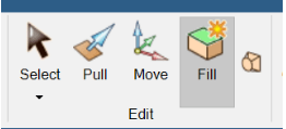
4. Press Fill on the ribbon bar. You should see that the geometry of the 3 rounded edges connected to that corner has been extended to remove the rounded corner (and the Select tool on the Ribbon bar has returned to active state)

5. Click once more on the Fill tool on the Ribbon bar to activate (note that it remains active this time because there is no part of the model selected)
6. Now Left click on one of the rounded edges between any 2 side faces of the cube and press Enter (you should see that the geometry of the 2 flat sides has extended to remove the rounded edge)
7. Repeat step 6 on the other rounded edges to remove them (note that the Fill tool remains active for the sequence of actions)
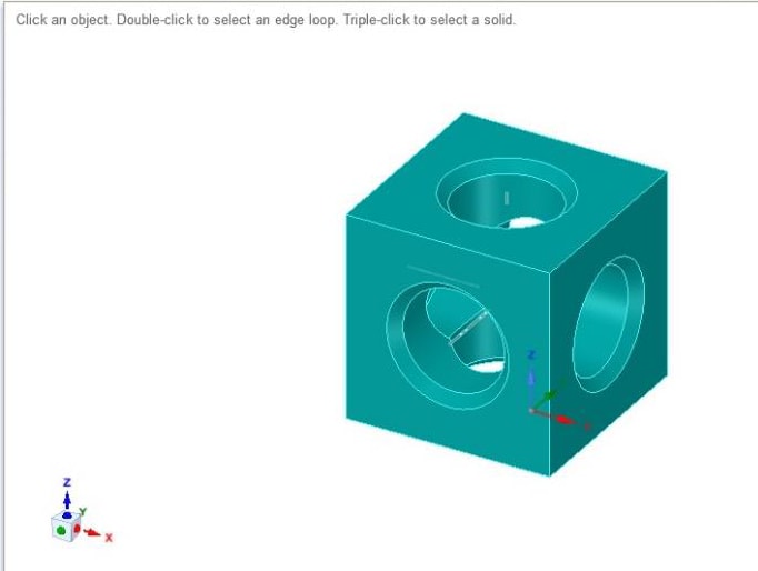
8. Now select (by Left clicking) one of the cylindrical surfaces inside the cube and press Enter. You should see that the cylindrical hole has closed off into a conical depression. This is because the Fill tool, as described in the preamble, has used the surrounding geometry to replace the filled feature, in this case the 45-degree chamfer.
9. Left click on the Undo tool to reinstate the cylindrical hole
10. Left click on the chamfered edge of the hole to select it. Use the selection tab on the left-hand options pane to group select all equally sized chamfers.
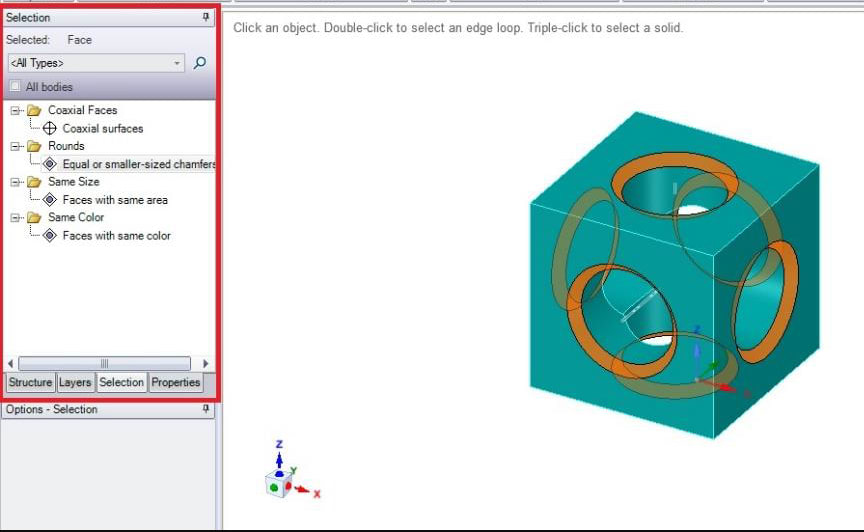
11. Press Enter to remove the chamfers.
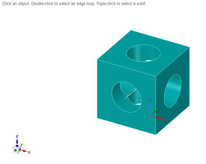
12. Now Left click on the outer edge of a hole to select it again and press Enter to fill the hole and restore a closed flat face to the cube (because this time the Fill tool has used the geometry of the face of the cube to replace the hole)

13. Open the PIN CUBE model (Select mode should be active on the Ribbon bar by default).
14. To use the Fill tool to remove one of the pins we need to use Ctrl Left Click x3 to multiple select the three surfaces of the pin (the cylinder, the round, and the end face) otherwise part of the pin will not be selected, and the tool will not know how to replace it.
15. Click on Fill on the Ribbon bar to remove the pin, restoring a flat side to the cube.
You may want to save these examples or continue to develop them. Another option for developing skill with the Fill tool would be to import a 3D model and modify it using the above functions.
Additional reading
First steps to Direct Modelling Part 1: Look at the Sketch, Select and Pull tools
First steps to Direct Modelling Part 2: Look at the Sketch, Select and Pull tools
First steps to Direct Modelling Part 3: Look at the Move tool
First steps to Direct Modelling Part 4: Look at the Fill Tool
First steps to Direct Modelling Part 5: Look at the Combine Tool