First steps to Direct Modelling Part 3: Look at the Move tool
Follow tutorial
 Dave from DesignSpark
How do you feel about this tutorial? Help us to provide better content for you.
Dave from DesignSpark
Thank you! Your feedback has been received.
Dave from DesignSpark
There was a problem submitting your feedback, please try again later.
Dave from DesignSpark
What do you think of this tutorial?
This tutorial requires:
DesignSpark Mechanical V6.0This tutorial is in progressive sections and will guide you with the main model creation commands in DesignSpark Mechanical. The first two sections will help you build two models (using the Sketch, Select and Pull tools) and the third section will show you how to assemble the models together (using a range of Move functions). Following sections will illustrate further skills, including Fill (removing features) and Combine (cutting into one model using another model or merging two models together). You will then be able to design your own parts and assemble them using the same tools and functions.
The models created in sections 1 & 2 are used in later tutorials. If you have not completed section 1 and 2 but need to work on later sections these are attached to the tutorial.
SECTION 3 - Assembling cubes
1. Open DesignSpark Mechanical and close the welcome screen
2. Ensure your PIN CUBE and HOLED CUBE designs are open
3. Create a new file containing both parts by triple clicking on the PIN CUBE and using the Copy command from the top left on the ribbon bar (remember that triple-click select only selects item as a solid - to select devices with their component details you should either select from the structure tree or use the select component tool)
4. Left click into the HOLED CUBE design and use the Paste command to place the PIN CUBE into the design (the imported model will often coincide with the existing model to some extent at this stage – this is not a problem)
5. Save the file as CUBE ASSEMBLY
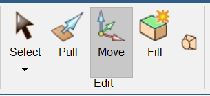
6. Select the Move function from the ribbon bar.
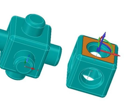
7. A move anchor will appear in the model with 3 coloured axial arrows. Left click and drag one of the arrows to move the imported cube away from its partner shape so there is clear space between them.
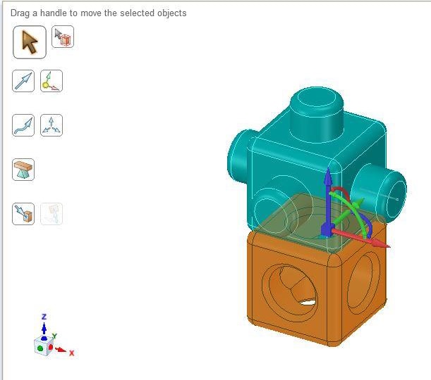
8. To assemble the cubes together as they would physically appear you will need to use the Move -> Up to function a number of times to position the cubes in the nominal x, y and z axes.
While the cube is still selected for Move, grab the central boss of the Move anchor and position it so it sits on a face of the cube which you wish to align with the partner cube.
Left click on the arrow of the Move anchor which sits in the axis you need to use to do the first align.
A command icon menu will appear. Left click on the 3rd icon (a green arrow pointing at a rectangular sketch frame) and then Left click on the face of the partner cube which you wish to align with (a point or edge can be selected if they sit on that face). The two faces should now be in line.
9. Repeat the above step until you have matched all 3 axes of the cubes. They should now be assembled.
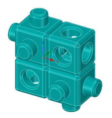
10. To expand the assembly, create additional cubes of each version by triple clicking, copying, and pasting and assemble them together in the same way as above.
Additional reading
First steps to Direct Modelling Part 1: Look at the Sketch, Select and Pull tools
First steps to Direct Modelling Part 2: Look at the Sketch, Select and Pull tools
First steps to Direct Modelling Part 3: Look at the Move tool
First steps to Direct Modelling Part 4: Look at the Fill Tool
First steps to Direct Modelling Part 5: Look at the Combine Tool