Building a Valve Amplifier Part 3: Testing the Prototype, Adjusting the Design and Planning the Enclosure
Follow article
 Dave from DesignSpark
How do you feel about this article? Help us to provide better content for you.
Dave from DesignSpark
Thank you! Your feedback has been received.
Dave from DesignSpark
There was a problem submitting your feedback, please try again later.
Dave from DesignSpark
What do you think of this article?
Building a brand new valve amplifier using the RH84 design and off-the-shelf components.
In the previous posts, I introduced the RH84 design and covered the building of a single channel prototype. As the amplifier takes 315V for the HT supply, there are certain safety concerns to be taken into consideration. We decided that it should not be worked on by anyone by themselves and the safety tips on the Valve Heaven web site provided some sensible additional guidelines.
Warning: this is not a how-to guide, these are not safety instructions and you should not attempt working on high voltage equipment unless you are suitably qualified and comfortable doing so!
Finishing the Prototype
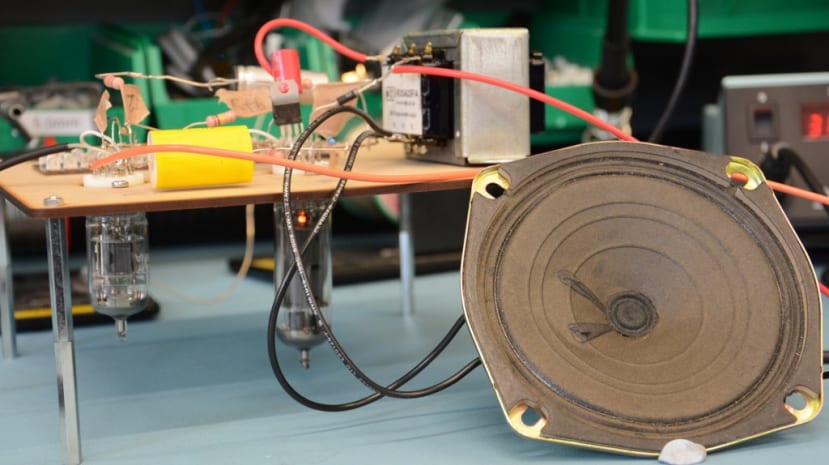
Now it was time to put the finishing touches to the single channel prototype and see how it performed. The first thing was to connect the audio transformer (123-7242) .
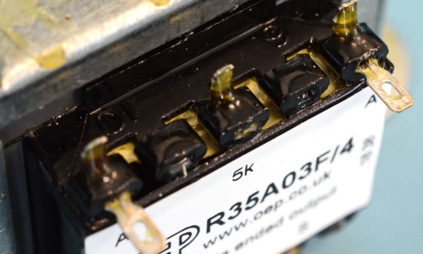
I referred to the datasheet PDF and found the pin numbers marked on the transformer, then worked out that we needed to connect the 315V supply to pin six, with pin 10 connecting to pin 7 on the EL84 valve.
We gave the circuit one last check and discovered that I needed to alter the connections to some of the pins on the 12AT7 valve. Not having worked with valves before, I had not realised that, being a dual-triode, it was in effect 2 valves in one (even though I had it marked as a “twin triode valve” in my initial plans!) This meant I needed to use either one side or the other and not mix and match connections as I had. This also resulted in a “light bulb moment” — I had wondered why, when I was looking at other examples of the RH84 amp, some had 3 valves rather than 4; I realised I could use both sides of the 12AT7 valve, one for each channel.
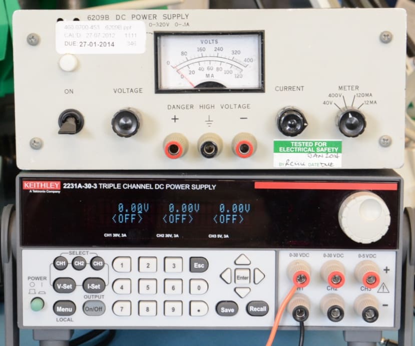
At this point, we were using bench power supplies as we have yet to build the power supply. A high voltage one was used for the 315V and our regular one to supply the 6.3V to the valve heaters.
We also opted to use an old speaker just in case it all went horribly wrong, and this was connected to the S and the 8-ohm pins of the audio transformer.

We initially just connected the 6.3V to see if the valves light up and discovered that only the EL84 did. We worked out that again, because the 12AT7 is a dual-triode and so has a double heater, rather than connecting one heater pin to 6.3V and the opposite one to ground, we needed to connect ground to the heater’s centre tap – pin 9. Once that was done we could see both valves were glowing and went ahead and connected the 315V supply.
We were pleased with the sound, especially considering the speaker we were using and that the audio source was a mobile ‘phone.
Documenting connections
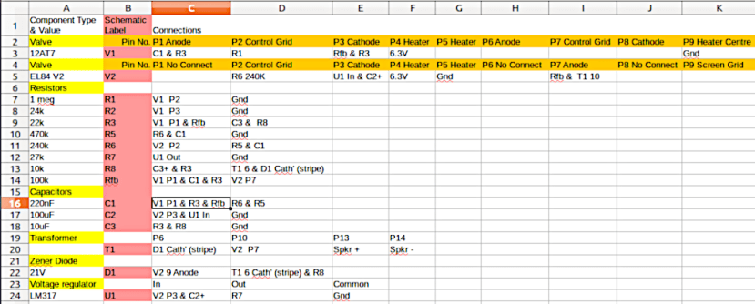
I am ashamed to say I had not done a particularly neat job of the soldering on the prototype, especially after I had made the alterations noted above. I wanted the final version to be much tidier and so needed to be sure that I had the optimum layout, and that I got everything in the right place first time. To this end, I produced a spreadsheet listing all the components and detailing their connections for a single channel. I then added a second sheet detailing a stereo version, taking into account the fact that I was now only using the one 12AT7 valve.
Enclosure and Layout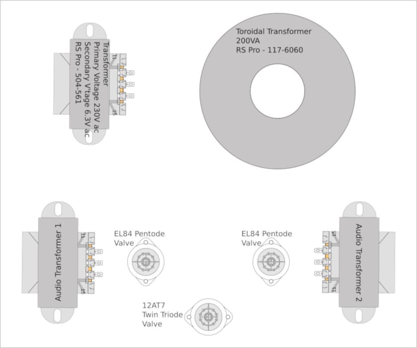
We are using the Hammond enclosure (867-3634) with a perforated cover (868-2629) . The base of the enclosure is to be covered in MDF with a dark wood veneer to give it that classic 1970s look.
The size of the enclosure provides plenty of room for all the parts.
I plan to have just the 3 valves and two audio output transformers on top of the enclosure. Most EL84 amps I have seen pictures have all of the transformers on view, but this way it should be a nice balance of parts on top and underneath the enclosure top panel. The front will have a power switch and indicator light and single volume control, with input, output and power sockets on the rear.
Next Steps
It was somewhat of a relief when the prototype worked so well, albeit with a few adjustments. I am now looking forward to putting both channels together, practising my point-to-point soldering and getting the power supply sorted out. There is also the enclosure to drill to mount the components and support the cover and veneer. So there is still a fair bit of work to do.