Building a Custom Stereo Spring Reverb in a Metal Toolbox
Follow article
 Dave from DesignSpark
How do you feel about this article? Help us to provide better content for you.
Dave from DesignSpark
Thank you! Your feedback has been received.
Dave from DesignSpark
There was a problem submitting your feedback, please try again later.
Dave from DesignSpark
What do you think of this article?
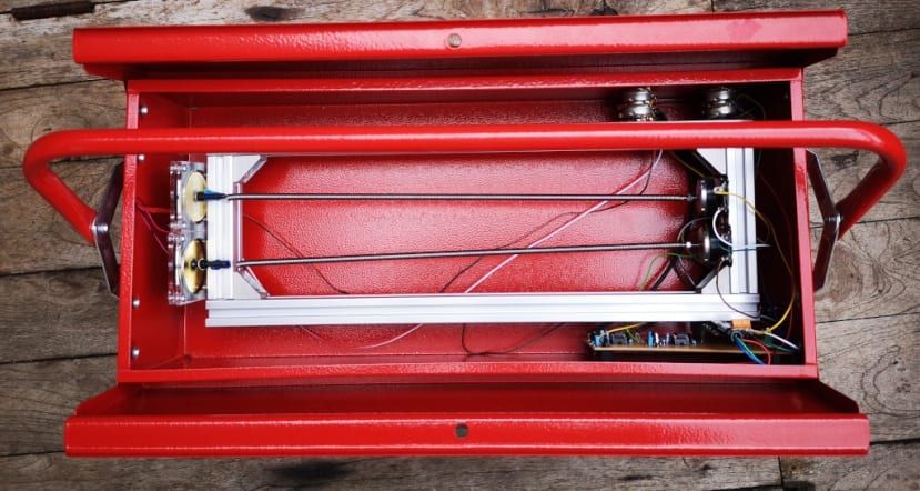
Putting together a stereo version of the spring reverb and fitting it in a metal toolbox.
In a previous blog post I wanted to see if I could build an effective spring reverb with off-the-shelf parts and for this used a piezo microphone (622-1584) , an audio exciter (121-8641) and some springs. For the final version I decided to support these on a frame made from 20 x 20 aluminium extrusion (850-8476) , as we had some lengths and fixings left over from previous projects. The reverb is to be housed in a red metal toolbox (773-9348) , which will need holes drilling to accommodate inputs, outputs, controls and the electronics.
Power supply
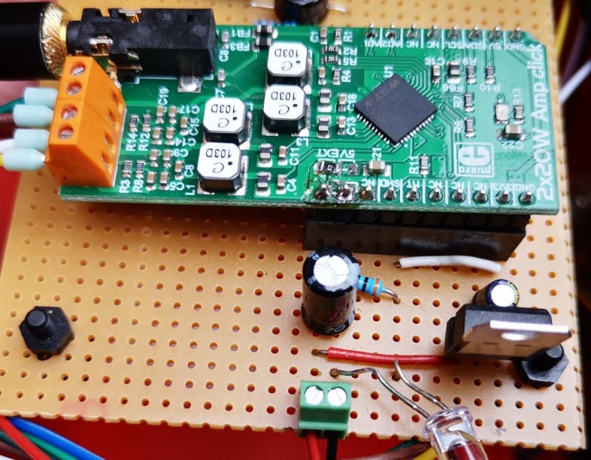
My first job was to mount the MikroElektronika 2 x 20 W Click Amp (165-1405) I was using to power the audio exciter on strip board and make a simple circuit for its power supply. As I had discovered when building my 12V speaker system, the amp requires both 3.3V and 12V power – the former for the control circuit and the latter for the amplifier itself. I used a Linear Voltage Regulator (686-9767) to convert my 12V supply to 3.3V. I also added a decoupling capacitor to my circuit again, referring to the 12V speakers I had built previously.
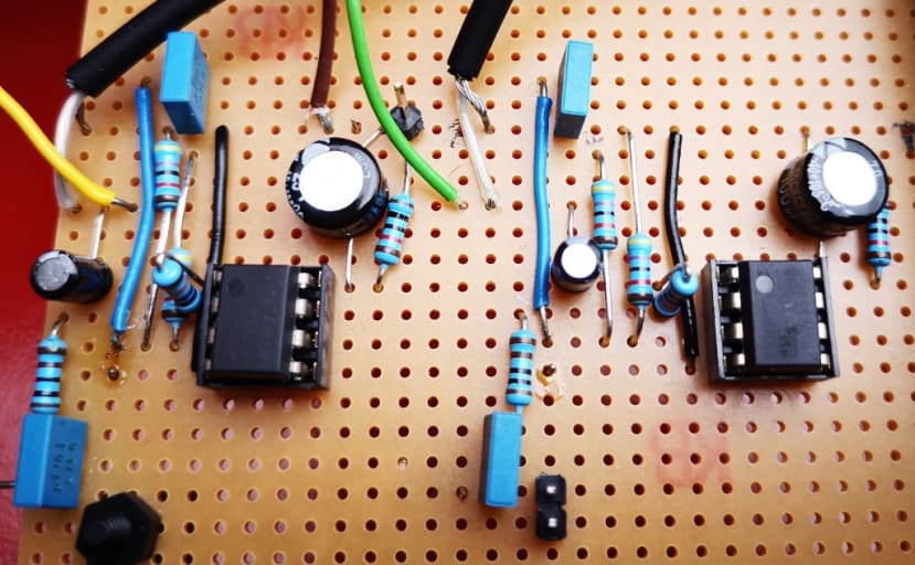
Next, I took the pre-amp I had put together on a breadboard and doubled it up to make it stereo and transferred it to the stripboard. As I was using a dual TL072 op amp (182-2413) for my pre-amp, I could have used a single one for my stereo circuit but decided just to make two of the proven circuits I had already tested, which made it simpler for me and would make troubleshooting easier in the event of any faults. I had plenty of room in my toolbox and had spare op-amps at my disposal.
The circuit then needed the addition of the input and output jack sockets (047-8015) , the two 100K dual-gang potentiometers (168-342) for level control, an LED (451-6543) as a power indicator and finally a barrel socket (487-832) for the 12V input — making sure the 2.1mm centre pole matched the plug on my power supply (139-2343) .
Mounting the springs
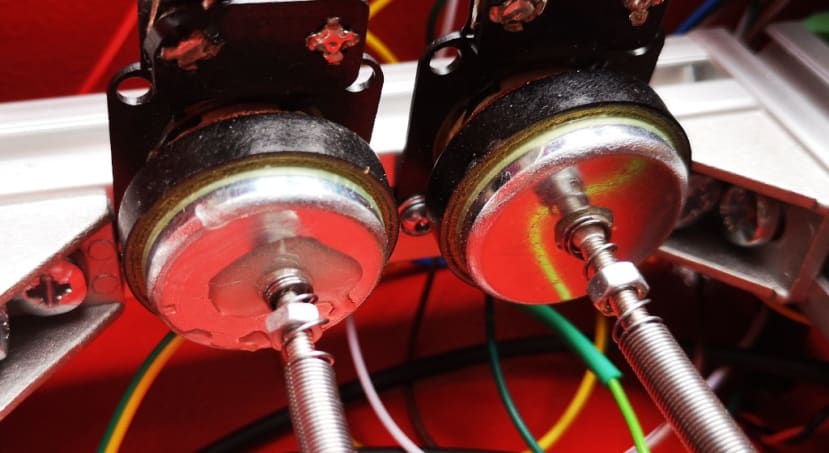
I had found that fixing screws to the audio exciters and microphones using epoxy resin (159-3957) worked well and, if I used long screws, I could adjust the tension of the springs. I reused the ones from my prototype and glued one more of each for my double spring arrangement.
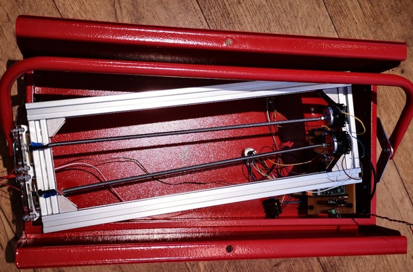
I then built a simple frame from four lengths of 20x20 aluminium extrusion (850-8476) using four right angle connectors (180-9136) , just wide enough to accommodate the two microphones side-by-side, which were mounted using roll-in T-slot nuts (180-9105) . I cut two lengths of spring to fit between the microphones and exciters under low tension.
Next, I soldered a stereo 3.5mm jack plug (395-1119) to the two exciters, with enough cable that it would reach the Click amplifier when everything was in the tin. I also connected the microphones to the strip board pre-amps, again with sufficient wire to fit in the toolbox.
Fitting it all in the toolbox
I drilled four 10mm holes in the side of the toolbox for the jack sockets and potentiometers, using a laser cut template to make sure they were all lined up neatly.
The circuit on its strip board is mounted on the side of the toolbox using four 5mm stand-offs (184-1957) , so needed four 3mm holes drilling and positioned so that the power LED poked through a small hole in the side of the toolbox, adjacent to the power socket.
The frame supporting the springs is also mounted on stand-offs – 30mm this time (184-1679) – secured to the base of the toolbox with screws which also fix four rubber feet in place and screwed into more roll-in T-nuts in the aluminium frame.
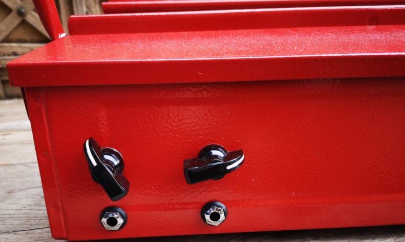
The potentiometers are finished off with the classic 60s style “chicken head” knobs (022-3742) .
Trying it out
Once everything was fitted in the toolbox it was time to try it out. I set up a simple percussion patch on my modular synth and routed the output through the reverb. It gives quite a distinctive spring reverb effect as you can hear in the video above, and disturbing the toolbox makes a really interesting “wobble” effect, which I like. The audio exciters powered by the click amp give out an audible sound amplified somewhat by the toolbox itself – again I like this, but I could probably reduce it by some kind of cushioning for the spring mount frame and possibly some acoustic foam lining for the toolbox.
This is no ordinary spring reverb and it definitely has its own sound, which is great – it introduces a physical, mechanical element to my electronic music which I am very pleased with.
For future developments, I am going to look at some more sophisticated wet/dry control over the signal rather than just balancing the input and output. I did try just using a potentiometer, with one end connected to the input, the other to the output and then taking the wet/dry mix output from the wiper, but sounded very “thin” so I reverted to my simple original setup. I think I am going to need some kind of buffering for a satisfactory sound – there are plenty of examples on the Internet.
I am already using the reverb in some of the music I am recording, particularly to give that unmistakable “spacey” sound to percussion tracks. And it is now referred to as the “Reverb in a Tin”.
Comments