Design of a Korg Nutube Amplifier Part 2: Prototype
Follow article
 Dave from DesignSpark
How do you feel about this article? Help us to provide better content for you.
Dave from DesignSpark
Thank you! Your feedback has been received.
Dave from DesignSpark
There was a problem submitting your feedback, please try again later.
Dave from DesignSpark
What do you think of this article?
This is the second in a multi-part series looking at the design of a Nutube-based guitar pedal. The first provided an introduction to vacuum tubes and if you missed it you can find this in Part 1. We left off having started to look at amplifier design and building a small test circuit.
Minimum circuit
The circuit above is the bare minimum required for a single-stage Nutube amplifier. It consists of the following parts:
- A 3v3 regulator, in this case, an LM317T
- An input stage
- Bias
- An output pull-up resistor
A regulator is required
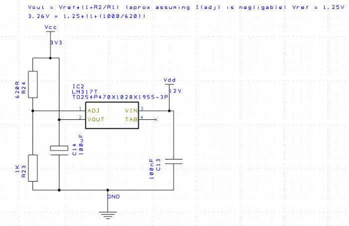
(Minimum LM317 Circuit, Excuse the reversed symbol!)
The Nutube requires a bias of around 2.5V and the filament needs 0.7V. The plate voltage is independent of this, so regardless of the operation voltage we need to provide these low voltage supplies.
Since the supplies are both low current (low mA) we can use a linear regulator, and just like the reference design, we can supply both of these from a single supply by resistively dividing it down.
Without getting too deep into the design a linear regulator, they are not efficient and will create heat while dropping voltages. The equation is P= (Vin-Vout) * I. In other words: if the voltage drop or current is high, so is the power. Keep this in mind if adding additional circuity to the design and don’t try taking Amps!
The advantage of using a linear regulator is it’s simple and we can keep system noise down in comparison to a switching regulator, at the expense of additional power loss.
Passive input/output
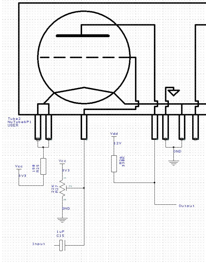
The input stage is just a 1uF capacitor for AC coupling.
The bias is created by using a 22k potentiometer to allow adjustment. This will in effect provide a variable supply of 0V – 3.3V. The current available from 22k is 150uA, which should be more than enough to provide the 6uA grid current.
The output is just a pull-up to the anode voltage (this will be the amp output voltage if the output is not AC coupled). The value of this pull-up can be adjusted to provide more output current, but it is important to stay within the power limit of the tube, which is 1.7mW.
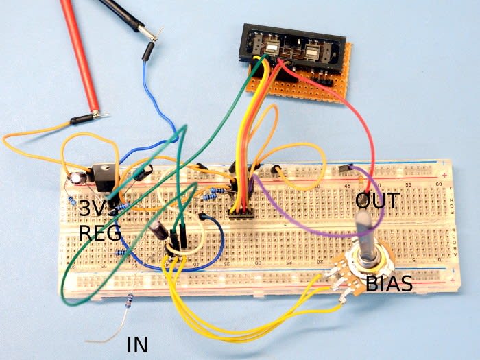
Test setup
To test the circuit we used an older sine wave generator we have, however living in the age of the Arduino you could simply build your own using an Arduino Due by following this tutorial. You will not be able to tell much of what’s going on with just a multimeter, so at this point, it would help if you had access to an oscilloscope.
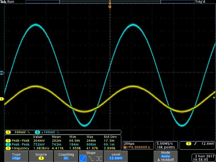
The first thing we need to do is to adjust the bias so that it sits at around 2.5V, by adjusting the pot a DVM can be used for this.
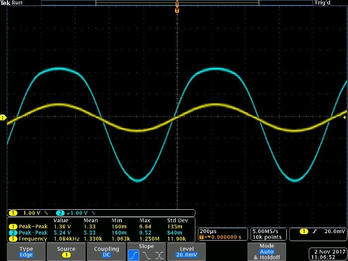
Following this, we inject a sine wave of around 200mV (quite a reasonable figure for a guitar pickup). As can be seen in the plot above, the Nutube is amplifying by around 3.5 times. This is to be expected since 5 times is a maximum and less is likely due to the load we are providing creating a potential divider….. But we have no load, or do we?
We are using an oscilloscope to measure the output and the equivalent circuit of the oscilloscope will end up being a resistor to ground of 1M impedance. This is only 3x the anode resistance so it will have a significant effect. This will need addressing in the final circuit as we cannot rely on a 1Meg (or more) input impedance in the device attached to our output.
Next, we can try a few other waveforms: a much higher frequency sine and a square wave (pretty nasty for an amp).
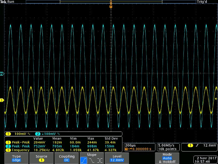
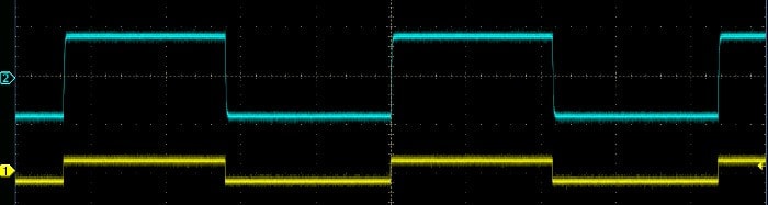
The high-frequency wave doesn’t look to be attenuated or distorted (visually anyway), so the Nutube is doing a good job and has sufficient bandwidth for audio at least. The square wave is interesting as it gives us an indication of the stability of the amplifier; the very sharp start/stop edges can be used to check something called step response. A stable or over damped system will not overshoot in such a case. The Nutube is definitely on the over-damped side of the equation. This is a good thing and should help produce a “sound effect” which will change the tone of the audio.
Next steps
At this point, we are almost ready for committing to CAD. We need to consider the output impedance and possibly the input too. Although if we are being fed by another device it will be expecting a 10k impedance, which we are not too far from using a 22k bias pot.
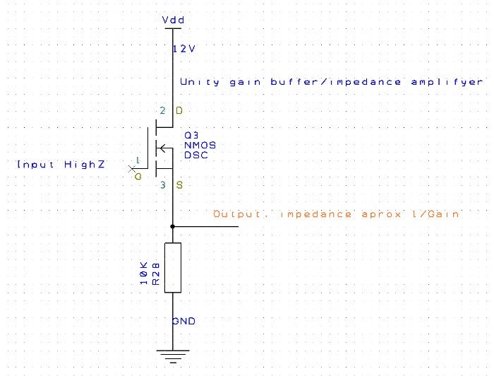
The output would benefit from some form of unity gain amplifier, which could be an op-amp or a simple FET/BJT circuit that will simply change from a high impedance to a low(er) impedance output. This output impedance may also be a concern for the cascading of two amplifiers, so AC coupling will be required.
We may want to try some audio through the design, although the breadboard is pretty noisy so we may not get exactly what we expect out of it. In addition, at this point, it would be a good idea to test out some unity gain output amplifiers too.
Final words
Having tested our Nutube and gained confidence in the circuit, this is a good point to break off and add the words, to be continued next time. If you are impatient, at this point building a stripboard circuit is quite possible and by the end of the next post, we will be at a point where we can commit to CAD and get a prototype built.
Comments