
 Dave from DesignSpark
こちらの記事について、内容・翻訳・視点・長さなど、皆様のご意見をお送りください。今後の記事製作の参考にしたいと思います。
Dave from DesignSpark
Thank you! Your feedback has been received.
Dave from DesignSpark
There was a problem submitting your feedback, please try again later.
Dave from DesignSpark
こちらの記事の感想をお聞かせください。
オーディオプロセッサCapeを備えたBelaソフトウェアと、BeagleBone Blackを使用して、自作DJマシン「Red Tin」用の高度なオーディオエフェクト端末を作成した。
シンプルなサンプルベースのサウンドエフェクトユニットとFuzz Boxギターペダルを組み立てた私は、次はもっと高度なものの組み立てに挑戦してRed Tinに組み込むことができたら楽しいだろうと思った。
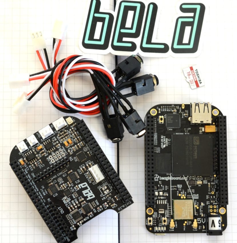
そこで以前から噂に聞いていたBelaプラットフォームを使ってみることにした。Belaプラットフォームは、BeagleBone Black用のオーディオプロセッサ「Cape」(BeagleBone用の拡張ボード規格。Raspberry Pi のHATや Arduinoのシールドにあたるもの) を備えたソフトウェアだ。さっそく手元にあるBeagleBone Black Wireless (125-2412) を使って挑戦してみた。
Belaはクイーン・メアリー(ロンドン大学)のAugmented Instruments Laboratoryのプロジェクトとして開発された。この研究所では、取り組んでいるプロジェクトのために汎用性が高く低レイテンシーなオーディオプラットフォームを必要としていたが、市販の製品では希望に合ったものが見つからなかったため、独自に構築したのだそうだ。詳細についてはこちらを参照してほしい。
初めて利用する場合
Belaにはとても役に立つ総合的な入門編ガイドがGithubで公開されているので、このガイドを参考に作業を始めた。
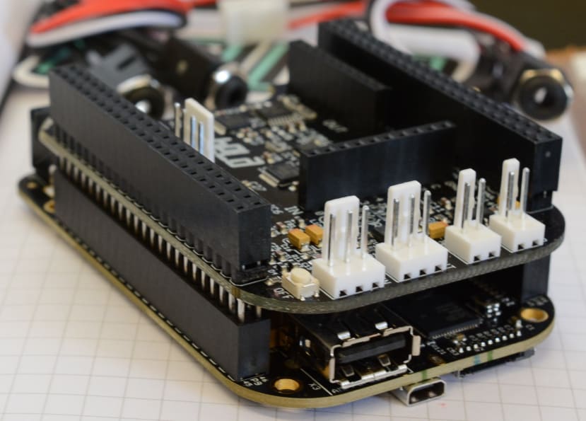
まずはBeagleBone BlackにBela Capeを取り付ける。その後Belaソフトウェアを設定した。私は仕事用コンピュータにUbuntuを使用し、Red TinでWindowsを使用しているので、ここでは両方のオペレーティングシステムの手順を説明する。
私はここからBelaのイメージファイルをダウンロードして解凍した。Ubuntuのコピーには、Belaが使用する.xzフォーマットを解凍するソフトウェアがすでにあったが、Windowsを使用している場合に.imgファイルを抽出するには7Zipなどを使用する必要がある。
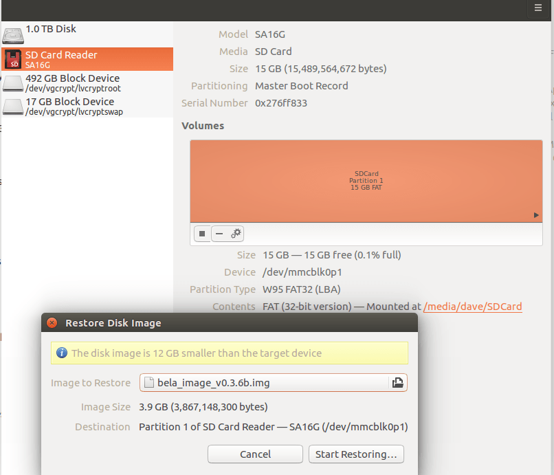
Ubuntuでは、.imgファイルを右クリックし、[Open with Disk Image Writer (ディスクイメージライタで開く)]を選択する。
次に、[Destination (宛先)]メニューでSDカードが選択されていることを確認し、[Start Restoring...(復元を開始...)]をクリックし、操作の実行を確認してパスワードを入力してから、イメージがカードに書き込まれるのを待つ。この操作でSDカード上の既存のデータが消去されるので注意してほしい。
コマンドラインから行う場合は、Bela githubページの「Belaイメージの点滅」セクションに手順が記載されている。Windowsを使用している場合は、Win32 Disk Imagerを使用することをお勧めする。
上記の操作を行い、Belaの.imgファイルが新たに書き込まれたMicro SDカードをBeagleBone Blackのスロットに挿入した後、Bela/Beagleboneを自分のコンピュータに接続し、接続が完了するのを待つ。これには少し時間がかかるだろう。その後は、Webブラウザを開いて、BeagleBone Black のIPアドレス( http://192.168.7.2 )にアクセスすれば完了だ。
するとブラウザウィンドウにBela IDEが表示されるはずなのだが、はじめは、Bela IDEが立ち上がらなかった。調べてみると、BeagleBone Blackは、デフォルトのO/Sイメージを含む内蔵eMMCメモリから起動することがわかった。Micro SDカードを介して強制的に起動するには、電源を切り、ユーザーボタンを押したままにして再接続し、ボタンを長押ししたままでMicro USBコネクタによって4つのLEDのグループが活動を示し始めるまで待つ。

上の図の小さなボタンは、Bela Capeを取り付けた状態では手が届かなくなるので、先に取り外しておく方が簡単だろう。
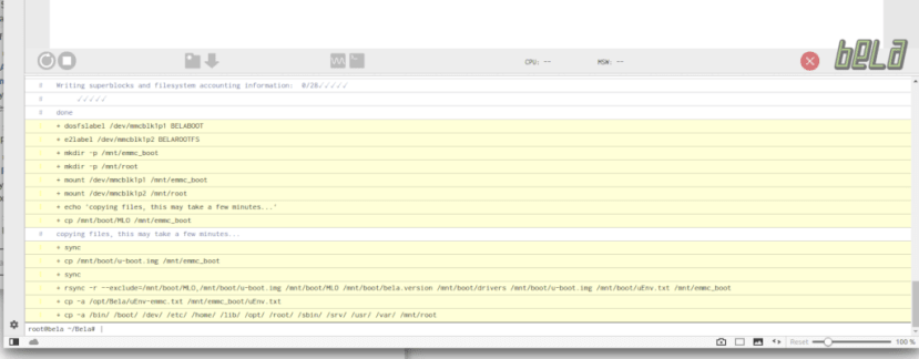
Bela IDEに入ることができたら、IDEの下部にあるコンソールセクションに次のコマンドを実行する。
/opt/Bela/bela_flash_emmc.sh
BelaイメージがeMMC上にあれば自動的にそこから起動するはずなので、私は電源を切り、Micro SDを取り外し、Bela Capeを交換してから再起動した。予想通り、今回はBelaイメージから起動した。
Belaハードウェア
Bela Capeにはコネクタが多数ある。以下はその一部だ。
- オーディオ入力: 44.1kHzで16ビットステレオオーディオ入力
- オーディオ出力: 44.1kHzで16ビットステレオオーディオ出力
- オーディオ電源出力: 1W 8Ωスピーカーアンプ(DCジャックから電源供給時に利用可能) x 2
- アナログ入力: 22.05kHzで16ビットアナログ入力 x 8
- アナログ出力: 22.05kHzで16ビットアナログ出力 x 8
- デジタルチャネル: 44.1kHz/88.2kHzでデジタルGPIO x 16
また、アナログI/Oは44.1kHzで4チャンネル又は88.1kHzで2チャンネルとなるようソフトウェアで設定可能だ。
Cape には、3.5mmステレオジャックソケットをオーディオ入出力コネクタに接続するためのケーブルが付属しているので便利だ。
サンプルプログラムを試す

ここでいよいよ[Examples and Projects (サンプルとプロジェクト)]のページにあるサンプルをいくつか試してみようと考えた。
これはBela IDEに慣れるには良い方法であり、IDEのメニューにはすべてのサンプルのコードへのリンクがあった。
鳴らしてみよう
#include <Bela.h>
#include <cmath>

float gFrequency = 440.0;
float gPhase;
float gInverseSampleRate;

bool setup(BelaContext *context, void *userData)
{
	gInverseSampleRate = 1.0 / context->audioSampleRate;
	gPhase = 0.0;

	return true;
}

void render(BelaContext *context, void *userData)
{
	for(unsigned int n = 0; n < context->audioFrames; n++) {
		float out = 0.8f * sinf(gPhase);
		gPhase += 2.0f * (float)M_PI * gFrequency * gInverseSampleRate;
		if(gPhase > M_PI)
			gPhase -= 2.0f * (float)M_PI;

		for(unsigned int channel = 0; channel < context->audioOutChannels; channel++) {
			audioWrite(context, n, channel, out);
		}
	}
}

void cleanup(BelaContext *context, void *userData)
{

}


/**
\example sinetone/render.cpp
Producing your first bleep!
---------------------------
This sketch is the hello world of embedded interactive audio. Better known as bleep, it
produces a sine tone.
The frequency of the sine tone is determined by a global variable, `gFrequency`.
The sine tone is produced by incrementing the phase of a sin function
on every audio frame.
In render() you'll see a nested for loop structure. You'll see this in all Bela projects.
The first for loop cycles through 'audioFrames', the second through 'audioChannels' (in this case left 0 and right 1).
It is good to familiarise yourself with this structure as it's fundamental to producing sound with the system.
*/
私は正弦波発生器の作成から始めた。これはまったく簡単で、Bela IDEにコードを読み込み、大きな緑色の実行ボタンをクリックするだけだ。付属のアダプタケーブルを使用してヘッドフォンを接続すると、確かに正弦波トーンが聞こえた。
上記のコードでわかるように、各サンプルの最後の部分はコメントとしてコードの実行内容を包括的に説明している。[The frequency of the sine tone is determined by a global variable, `gFrequency`(正弦波トーンの周波数はグローバル変数の`gFrequency`で決定される)]という説明があるので、コードの中でこの変数を見つけておけば、簡単に値を変更してコードを再実行し、サウンドの違いを耳で確かめることできる。
LED VUメーター(ボリュームメーター)
これは組み立てるのに少し時間がかかった。必要な部品は次のとおりである。
- 小型ブレッドボード (102-9147)
- 470Ω抵抗器 (683-3749) x 10
- 緑のLED (228-6004) x 7
- 黄のLED (228-6010) x 1
- 黄のLED (228-5988) x 2
部品さえそろっていれば、あとはただ組み立てるだけなので、あっという間に配線して Cape に接続できた。コードはIDEに読み込まれて実行されている。ここで私は、サンプルではLEDが前後逆になっていることに気付いた。黄色と赤のLEDを下部の3つの緑色LEDと交換し、全体をひっくり返すこともできたが、そうすると配線がめちゃくちゃになってしまう。そのため、配線の順序を逆にすることで、期待どおりの動作をさせることができた。
ディレイ
// Simple Delay on Audio Input with Low Pass Filter

#include <Bela.h>

#define DELAY_BUFFER_SIZE 44100

// Buffer holding previous samples per channel
float gDelayBuffer_l[DELAY_BUFFER_SIZE] = {0};
float gDelayBuffer_r[DELAY_BUFFER_SIZE] = {0};
// Write pointer
int gDelayBufWritePtr = 0;
// Amount of delay
float gDelayAmount = 1.0;
// Amount of feedback
float gDelayFeedbackAmount = 0.999;
// Level of pre-delay input
float gDelayAmountPre = 0.75;
// Amount of delay in samples (needs to be smaller than or equal to the buffer size defined above)
int gDelayInSamples = 22050;

// Butterworth coefficients for low-pass filter @ 8000Hz
float gDel_a0 = 0.1772443606634904;
float gDel_a1 = 0.3544887213269808;
float gDel_a2 = 0.1772443606634904;
float gDel_a3 = -0.5087156198145868;
float gDel_a4 = 0.2176930624685485;

// Previous two input and output values for each channel (required for applying the filter)
float gDel_x1_l = 0;
float gDel_x2_l = 0;
float gDel_y1_l = 0;
float gDel_y2_l = 0;
float gDel_x1_r = 0;
float gDel_x2_r = 0;
float gDel_y1_r = 0;
float gDel_y2_r = 0;

bool setup(BelaContext *context, void *userData)
{

    return true;
}

void render(BelaContext *context, void *userData)
{

    for(unsigned int n = 0; n < context->audioFrames; n++) {

        float out_l = 0;
        float out_r = 0;

        // Read audio inputs
        out_l = audioRead(context,n,0);
        out_r = audioRead(context,n,1);

        // Increment delay buffer write pointer
        if(++gDelayBufWritePtr>DELAY_BUFFER_SIZE)
            gDelayBufWritePtr = 0;

        // Calculate the sample that will be written into the delay buffer...
        // 1. Multiply the current (dry) sample by the pre-delay gain level (set above)
        // 2. Get the previously delayed sample from the buffer, multiply it by the feedback gain and add it to the current sample
        float del_input_l = (gDelayAmountPre * out_l + gDelayBuffer_l[(gDelayBufWritePtr-gDelayInSamples+DELAY_BUFFER_SIZE)%DELAY_BUFFER_SIZE] * gDelayFeedbackAmount);
        float del_input_r = (gDelayAmountPre * out_r + gDelayBuffer_r[(gDelayBufWritePtr-gDelayInSamples+DELAY_BUFFER_SIZE)%DELAY_BUFFER_SIZE] * gDelayFeedbackAmount);

        // ...but let's not write it into the buffer yet! First we need to apply the low-pass filter!

        // Remember these values so that we can update the filter later, as we're about to overwrite it
        float temp_x_l = del_input_l;
        float temp_x_r = del_input_r;

        // Apply the butterworth filter (y = a0*x0 + a1*x1 + a2*x2 + a3*y1 + a4*y2)
        del_input_l = gDel_a0*del_input_l
                    + gDel_a1*gDel_x1_l
                    + gDel_a2*gDel_x2_l
                    + gDel_a3*gDelayBuffer_l[(gDelayBufWritePtr-1+DELAY_BUFFER_SIZE)%DELAY_BUFFER_SIZE]
                    + gDel_a4*gDelayBuffer_l[(gDelayBufWritePtr-2+DELAY_BUFFER_SIZE)%DELAY_BUFFER_SIZE];

        // Update previous values for next iteration of filter processing
        gDel_x2_l = gDel_x1_l;
        gDel_x1_l = temp_x_l;
        gDel_y2_l = gDel_y1_l;
        gDel_y1_l = del_input_l;

        // Repeat process for the right channel
        del_input_r = gDel_a0*del_input_r
                    + gDel_a1*gDel_x1_r
                    + gDel_a2*gDel_x2_r
                    + gDel_a3*gDelayBuffer_r[(gDelayBufWritePtr-1+DELAY_BUFFER_SIZE)%DELAY_BUFFER_SIZE]
                    + gDel_a4*gDelayBuffer_r[(gDelayBufWritePtr-2+DELAY_BUFFER_SIZE)%DELAY_BUFFER_SIZE];

        gDel_x2_r = gDel_x1_r;
        gDel_x1_r = temp_x_r;
        gDel_y2_r = gDel_y1_r;
        gDel_y1_r = del_input_r;

        //  Now we can write it into the delay buffer
        gDelayBuffer_l[gDelayBufWritePtr] = del_input_l;
        gDelayBuffer_r[gDelayBufWritePtr] = del_input_r;

        // Get the delayed sample (by reading `gDelayInSamples` many samples behind our current write pointer) and add it to our output sample
        out_l += gDelayBuffer_l[(gDelayBufWritePtr-gDelayInSamples+DELAY_BUFFER_SIZE)%DELAY_BUFFER_SIZE] * gDelayAmount;
        out_r += gDelayBuffer_r[(gDelayBufWritePtr-gDelayInSamples+DELAY_BUFFER_SIZE)%DELAY_BUFFER_SIZE] * gDelayAmount;

        // Write the sample into the output buffer -- done!
        audioWrite(context, n, 0, out_l);
        audioWrite(context, n, 1, out_r);
    }

}

void cleanup(BelaContext *context, void *userData)
{

}

/**
\example delay/render.cpp
ここで私はエフェクトを試したくなった。何と言っても私の目的は、これをエフェクトモジュールに使用することだったからだ。
他のサンプルと同様に、目的のコードがIDEの右側のセクションに見つかった。電球アイコンをクリックしてアクセスする[Code Examples Section (コード例セクション)]に記載されている。
私は今こそ、スタンドアロンのエフェクトジェネレータでは不可欠な、コンピュータへの接続をせず起動時にスケッチを読み込む方法を学ぶべきだと思った。
まず、IDEのフォルダアイコンをクリックし、[Save project as (プロジェクトに名前を付けて保存)]ボタンをクリックして[Delay (ディレイ)]と名前を付け、[Save (保存)]をクリックして、ディレイコードをプロジェクトとして保存した。次に[Project Settings (プロジェクト設定)] (歯車アイコン)に移動し、[Run project on boot (起動時にプロジェクトを実行)]の横にあるドロップダウンをクリックし、新しく保存した[Delay (ディレイ)]プロジェクトを選択した。ここでBeagleBoneをシャットダウンしてコンピュータから取り外した。別の電源で電源をオンにして起動すると、フルエフェクトでディレイを聞くことができた。
Tremelo
Tremoloの速度は、Cape の1番目と3番目のピンの3.3VとGNDに接続された10K半固定抵抗器 (249-9200) によって制御され、2番目の真ん中のピンはanalogIn 0に接続する。
DJソフトウェアで正弦波をループで実行し、エフェクトがどのように聴こえるかを明確に把握できるようにした。
次のステップ
現在私は、BeagleBone Black とBela Capeを1つのモジュールとして組み立て、これを私が組み立てたサウンドエフェクトモジュールと似たRed Tinに取り付けることを計画している。また、複数のエフェクトをロードし、ケースに取り付けたボタンで切り替える方法を考え出す必要性も感じている。Belaで組み立てたギターエフェクトボックスでまさにこの動作をする例があるので、これは可能なはずだ。