
 戴夫来自 DesignSpark
你觉得这篇文章怎么样? 帮助我们为您提供更好的内容。
戴夫来自 DesignSpark
Thank you! Your feedback has been received.
戴夫来自 DesignSpark
There was a problem submitting your feedback, please try again later.
戴夫来自 DesignSpark
你觉得这篇文章怎么样?
使用 BeagleBone Black SBC 和带音频处理器 cape 的 Bela 软件为 Red Tin 搭建高级音频效果装置。
在搭建了一个简单的基于样本的声音效果装置和一个 Fuzz Box 吉他踏板之后,我想尝试搭建一个可以集成 Red Tin 的更高级装置,应该会很有趣。
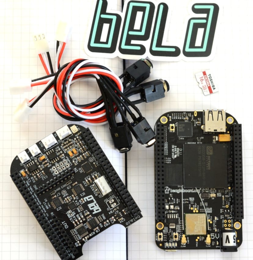
我听说过 Bela 平台、软件以及音频处理器“cape”(类似于 Raspberry Pi HAT 或 Arduino 扩展板,但适用于 BeagleBone Black 开发板),决定使用已有的 BeagleBone Black Wireless (125-2412) 进行尝试。
Bela 是伦敦玛丽女王大学隶属的乐器增强实验室的研发项目。当时该实验室需要一个多用途、低延迟的音频平台来支持正在进行的项目,但却发现没有“现成”的设备可用,于是搭建了自己的平台。您可以在此处阅读故事详情。
入门
Github 页面上有非常实用和详细的 Bela 入门指南,我就是从这里开始的。
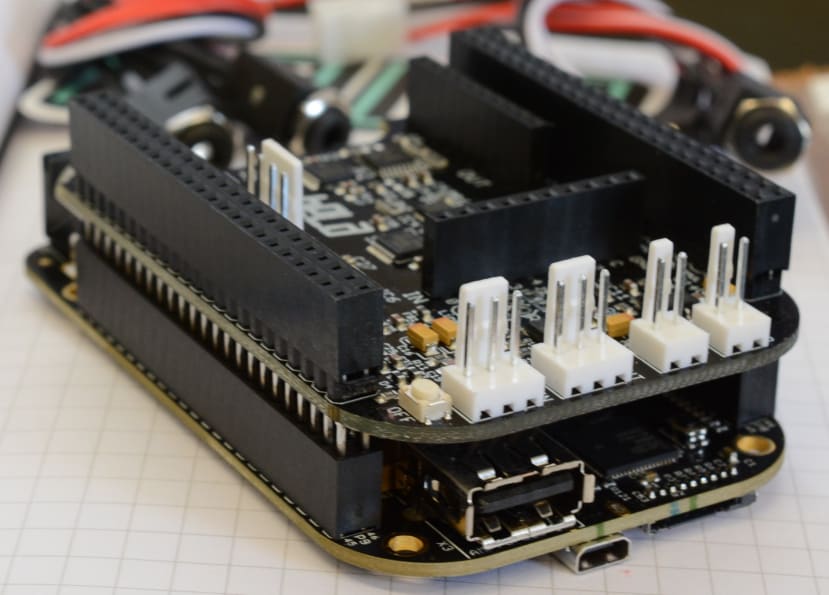
第一步是将 Bela cape 安装在 BeagleBone Black 上,然后就可以安装 Bela 软件了。我在工作计算机上使用 Ubuntu,而在 Red Tin 上安装了 Windows,下面我将介绍这两种操作系统的安装步骤。
我从这里下载了 Bela 映像并解压缩。我的 Ubuntu 副本中已包含相关软件,可解压缩 Bela 使用的 .xz 格式。但是如果您使用的是 Windows,则可能需要使用 7Zip 这类软件来提取 .img 文件。
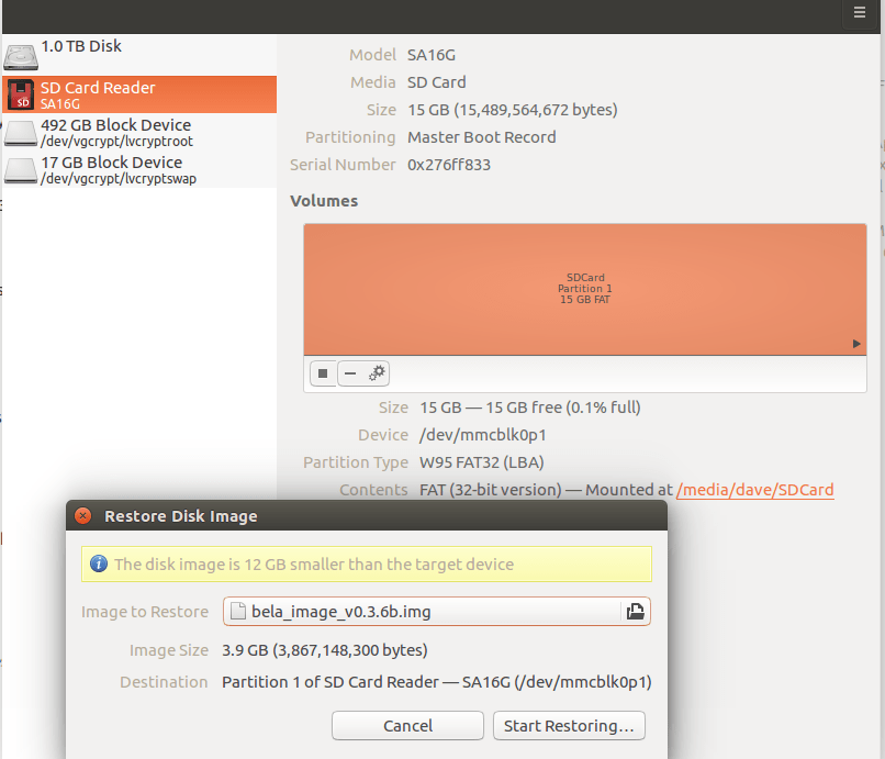
在 Ubuntu 中,您可以右键单击 .img 文件并选择“使用磁盘映像写入器打开”。
然后,确保您在“目标位置”菜单中选择 SD 卡,点击“开始恢复...”,确认执行此操作,输入您的密码,然后等待映像写入卡中。这一步将擦除 SD 卡上现有的所有数据!
如果您更喜欢从命令行执行此操作,可在 Bela Github 页面的“闪存 Bela 映像”部分找到说明。如果您使用的是 Windows,则建议使用 Win32 Disk Imager。
完成上述步骤,并将含有新写入的 Bela 映像的 Micro SD 卡插入 BeagleBone Black 插槽后,我将 Bela/Beaglebone 连接到我的计算机并等待连接。这需要一段时间,但蓝色闪烁的 LED 灯确认了过程正在进行中。接着只需打开网页浏览器并访问 BeagleBone Black 的 IP 地址 http://192.168.7.2 即可。
然后,您应该会在浏览器窗口中看到 Bela IDE。只是我看到的是不带 Bela 标识的 Beaglebone 页面。经过调查后,我发现 BeagleBone Black 从其内置的 eMMC 存储器启动,而该存储器包含默认的 O/S 映像。如需强制从 Micro SD 卡中启动,可以关闭其电源,按住用户按钮,然后重新连接,保持按钮不松开,直到 Micro USB 连接器旁的 4 个 LED 灯组指示进入活动状态为止。

在已安装 Bela cape 的情况下,这个小按钮不易按到,因此取下它更方便操作。
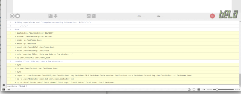
进入 Bela IDE 后,我可以通过将以下命令输入 IDE 底部的控制台部分来运行它:
/opt/Bela/bela_flash_emmc.sh
现在 eMMC 上已有 Bela 映像,可自动从该映像启动,于是我关闭电源,取出 Micro SD 卡,换上 Bela cape,然后重新启动。这一次从 Bela 映像启动成功。
Bela 硬件
Bela cape 上有许多连接器,其中包括:
- 音频输入:44.1kHz 16 位立体声音频输入
- 音频输出:44.1kHz 16 位立体声音频输出
- 音频功率输出:2 x 1W 8 Ω 扬声器放大器(由直流插孔供电时可用)
- 模拟输入:22.05kHz 8 x 16 位模拟输入
- 模拟输出:22.05kHz 8 x 16 位模拟输出
- 数字通道:16 个 44.1kHz 或 88.2kHz 数字 GPIO
模拟输入/输出也可通过软件配置成 44.1kHz 四声道或 88.1kHz 二声道。
cape 随附电缆,可用于将 3.5mm 立体声插孔连接到音频输入和输出连接器,操作更简单。
尝试示例

我认为现在最好的做法是运行一些示例,而“示例和项目”页面上可以找到一些示例。
这是熟悉 Bela IDE 操作的好方法,同时我发现,IDE 菜单中的所有示例代码均有链接。
发出“哔哔”声!
#include <Bela.h>
#include <cmath>

float gFrequency = 440.0;
float gPhase;
float gInverseSampleRate;

bool setup(BelaContext *context, void *userData)
{
	gInverseSampleRate = 1.0 / context->audioSampleRate;
	gPhase = 0.0;

	return true;
}

void render(BelaContext *context, void *userData)
{
	for(unsigned int n = 0; n < context->audioFrames; n++) {
		float out = 0.8f * sinf(gPhase);
		gPhase += 2.0f * (float)M_PI * gFrequency * gInverseSampleRate;
		if(gPhase > M_PI)
			gPhase -= 2.0f * (float)M_PI;

		for(unsigned int channel = 0; channel < context->audioOutChannels; channel++) {
			audioWrite(context, n, channel, out);
		}
	}
}

void cleanup(BelaContext *context, void *userData)
{

}


/**
\example sinetone/render.cpp
Producing your first bleep!
---------------------------
This sketch is the hello world of embedded interactive audio. Better known as bleep, it
produces a sine tone.
The frequency of the sine tone is determined by a global variable, `gFrequency`.
The sine tone is produced by incrementing the phase of a sin function
on every audio frame.
In render() you'll see a nested for loop structure. You'll see this in all Bela projects.
The first for loop cycles through 'audioFrames', the second through 'audioChannels' (in this case left 0 and right 1).
It is good to familiarise yourself with this structure as it's fundamental to producing sound with the system.
*/
我从正弦波发生器开始。先将代码载入 Bela IDE 中,然后点击大的绿色运行按钮,这一步很简单。我使用随附的适配器线缆连接耳机,并且确定可以听到正弦波的声音。
如以上代码所示,每个示例都在底部备注中给出详细的代码内容说明。正如上文所述“正弦音调的频率由全局变量‘gFrequency’决定”,因此在代码中找到该变量后,我可以轻松更改该值,重新运行代码并听到声音的变化。
LED 音量电平表
组装该装置需要花费一点时间。所需组件有:
- 一块小型试验电路板 (102-9147)
- 10 个 470 Ω 电阻器 (683-3749)
- 7 个绿色 LED (228-6004)
- 1 个黄色 LED (228-6010)
- 2 个红色 LED (228-5988)
一旦找齐元器件,组装过程相当简单,我很快就将它接线并连接到 cape 上,然后在 IDE 中加载代码并运行。这时我发现示例中的 LED 灯前后颠倒。如需修正,只需将黄色和红色 LED 灯与底部的三个绿色 LED 灯互换,然后将整块板反转即可,但是这样会使布线变得凌乱,因此通过反转接线顺序的简单方法进行修正,就能达到预期效果。
延迟
// Simple Delay on Audio Input with Low Pass Filter

#include <Bela.h>

#define DELAY_BUFFER_SIZE 44100

// Buffer holding previous samples per channel
float gDelayBuffer_l[DELAY_BUFFER_SIZE] = {0};
float gDelayBuffer_r[DELAY_BUFFER_SIZE] = {0};
// Write pointer
int gDelayBufWritePtr = 0;
// Amount of delay
float gDelayAmount = 1.0;
// Amount of feedback
float gDelayFeedbackAmount = 0.999;
// Level of pre-delay input
float gDelayAmountPre = 0.75;
// Amount of delay in samples (needs to be smaller than or equal to the buffer size defined above)
int gDelayInSamples = 22050;

// Butterworth coefficients for low-pass filter @ 8000Hz
float gDel_a0 = 0.1772443606634904;
float gDel_a1 = 0.3544887213269808;
float gDel_a2 = 0.1772443606634904;
float gDel_a3 = -0.5087156198145868;
float gDel_a4 = 0.2176930624685485;

// Previous two input and output values for each channel (required for applying the filter)
float gDel_x1_l = 0;
float gDel_x2_l = 0;
float gDel_y1_l = 0;
float gDel_y2_l = 0;
float gDel_x1_r = 0;
float gDel_x2_r = 0;
float gDel_y1_r = 0;
float gDel_y2_r = 0;

bool setup(BelaContext *context, void *userData)
{

    return true;
}

void render(BelaContext *context, void *userData)
{

    for(unsigned int n = 0; n < context->audioFrames; n++) {

        float out_l = 0;
        float out_r = 0;

        // Read audio inputs
        out_l = audioRead(context,n,0);
        out_r = audioRead(context,n,1);

        // Increment delay buffer write pointer
        if(++gDelayBufWritePtr>DELAY_BUFFER_SIZE)
            gDelayBufWritePtr = 0;

        // Calculate the sample that will be written into the delay buffer...
        // 1. Multiply the current (dry) sample by the pre-delay gain level (set above)
        // 2. Get the previously delayed sample from the buffer, multiply it by the feedback gain and add it to the current sample
        float del_input_l = (gDelayAmountPre * out_l + gDelayBuffer_l[(gDelayBufWritePtr-gDelayInSamples+DELAY_BUFFER_SIZE)%DELAY_BUFFER_SIZE] * gDelayFeedbackAmount);
        float del_input_r = (gDelayAmountPre * out_r + gDelayBuffer_r[(gDelayBufWritePtr-gDelayInSamples+DELAY_BUFFER_SIZE)%DELAY_BUFFER_SIZE] * gDelayFeedbackAmount);

        // ...but let's not write it into the buffer yet! First we need to apply the low-pass filter!

        // Remember these values so that we can update the filter later, as we're about to overwrite it
        float temp_x_l = del_input_l;
        float temp_x_r = del_input_r;

        // Apply the butterworth filter (y = a0*x0 + a1*x1 + a2*x2 + a3*y1 + a4*y2)
        del_input_l = gDel_a0*del_input_l
                    + gDel_a1*gDel_x1_l
                    + gDel_a2*gDel_x2_l
                    + gDel_a3*gDelayBuffer_l[(gDelayBufWritePtr-1+DELAY_BUFFER_SIZE)%DELAY_BUFFER_SIZE]
                    + gDel_a4*gDelayBuffer_l[(gDelayBufWritePtr-2+DELAY_BUFFER_SIZE)%DELAY_BUFFER_SIZE];

        // Update previous values for next iteration of filter processing
        gDel_x2_l = gDel_x1_l;
        gDel_x1_l = temp_x_l;
        gDel_y2_l = gDel_y1_l;
        gDel_y1_l = del_input_l;

        // Repeat process for the right channel
        del_input_r = gDel_a0*del_input_r
                    + gDel_a1*gDel_x1_r
                    + gDel_a2*gDel_x2_r
                    + gDel_a3*gDelayBuffer_r[(gDelayBufWritePtr-1+DELAY_BUFFER_SIZE)%DELAY_BUFFER_SIZE]
                    + gDel_a4*gDelayBuffer_r[(gDelayBufWritePtr-2+DELAY_BUFFER_SIZE)%DELAY_BUFFER_SIZE];

        gDel_x2_r = gDel_x1_r;
        gDel_x1_r = temp_x_r;
        gDel_y2_r = gDel_y1_r;
        gDel_y1_r = del_input_r;

        //  Now we can write it into the delay buffer
        gDelayBuffer_l[gDelayBufWritePtr] = del_input_l;
        gDelayBuffer_r[gDelayBufWritePtr] = del_input_r;

        // Get the delayed sample (by reading `gDelayInSamples` many samples behind our current write pointer) and add it to our output sample
        out_l += gDelayBuffer_l[(gDelayBufWritePtr-gDelayInSamples+DELAY_BUFFER_SIZE)%DELAY_BUFFER_SIZE] * gDelayAmount;
        out_r += gDelayBuffer_r[(gDelayBufWritePtr-gDelayInSamples+DELAY_BUFFER_SIZE)%DELAY_BUFFER_SIZE] * gDelayAmount;

        // Write the sample into the output buffer -- done!
        audioWrite(context, n, 0, out_l);
        audioWrite(context, n, 1, out_r);
    }

}

void cleanup(BelaContext *context, void *userData)
{

}

/**
\example delay/render.cpp
我现在很想尝试一些效果,因为我的最终目标是将它用于效果模块。
与其他示例一样,我在 IDE 的右侧部分找到了代码,这些代码列在“代码示例部分”中,点击灯泡图标即可访问。
我认为现在是学习如何在不连接计算机的情况下在启动时加载程序的好机会,因为这一点对于独立效果发生器至关重要。
首先,我将延迟代码另存为项目,方法是点击 IDE 中的文件夹图标,点击“项目另存为”按钮,并命名为“延迟”,再点击“保存”。接着打开“项目设置”(齿轮图标),点击“启动时运行项目”旁边的下拉菜单,并选择新保存的延迟项目。我关闭 BeagleBone 并将它从计算机断开。然后,我使用独立电源为它供电,启动后就能听到充分的延迟音效。
Tremelo
Tremolo 的速度由 10K 电位器 (249-9200) 控制,该电位器连接到 cape 的第 1 个和第 3 个引脚上的 3.3V 和 GND,其中第 2 个中间引脚连接到 analogIn 0。
我在 DJ 软件中循环运行正弦波,以便清楚地感受效果声音。
后续步骤
现在我的计划是将 BeagleBone Black 和 Bela cape 集成到适合 Red Tin 的模块中,该模块与我搭建的声音效果模块类似。我还需要了解如何加载多个效果,并且如何使用安装在外壳上的按钮进行切换。我知道这应该是可行的,因为有基于 Bela 的吉他效果盒子示例可以做到这些。