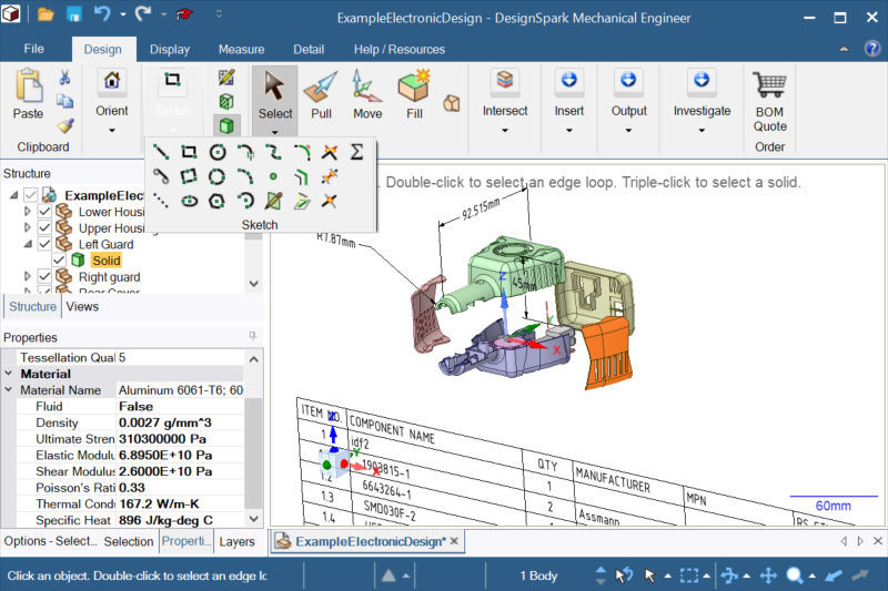
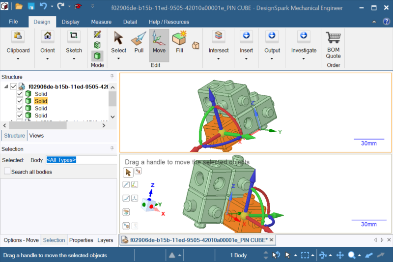
- DesignSpark Mechanicalの基本操作やファイルの新規作成方法
DesignSpark Mechanicalを学ぶ
こちらのチュートリアルで以下の事を学べます。
- ダイレクトモデリング方式とプル(押し出し)機能を使った3Dモデリング方法
- オンラインライブラリから3Dモデル(部品やアセンブリ)を設計ファイルにインポートする方法
- ジオメトリエラーや操作エラーなどモデリング上の一般的な問題の解決方法
- 3Dプリンタ用のSTLファイルの出力方法と注意点
チュートリアル
初級、中級、上級に分かれたステップバイステップのチュートリアルです。

はじめに
ソフトウェアのダウンロード、インストール、ログインの方法

DesignSpark Mechanicalのユーザーインターフェース
ソフトウェアのインターフェースや基本操作を学びます

DesignSpark Mechanicalの新規ファイル作成
"初めて3Dデータを作成するための手順を学びます。

3Dモデルをダウンロード
オンラインライブラリから部品の3Dモデルをダウンロードする方法を学びます。
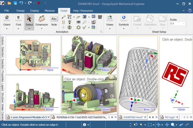
DesignSpark Mechanicalでの3Dモデリングのテクニック
ソフトウェア内の機能を駆使して作成したい3D形状に仕上げていく方法を学びます。

3Dデータを3Dプリンタで出力する
作成した3Dデータを3Dプリンタで出力するための方法を学びます。

異動の多いチームメンバーのライセンス管理が簡単に!
マルチシートライセンスなら、チーム員のライセンスの管理が容易になります。
- メンバーの増減・異動・担当変更に合わせ、ライセンスの割り当てをユーザ側で柔軟に変更可能
- メンバー全員が3種の設計ツールを利用
- シート数が増えるほど割引率アップ
DesignSpark Mechanicalのコミュニティ
DesignSpark Mechanicalのユーザと相談できるコミュニティーです。多言語混在コミュニティーなので日本語でも投稿頂けます。
I cannot export this assembly as an stp, after some diagnosis if i delete GP02-0240 and 0247 from sub assembly GP02-5011, I can then export to stp. Both these parts can be opened and exported on their own. Geometry check is all clear. Any idea how to fix this, note the parts have drawings with them, I'd rather not re-do.
Just to confirm, I have the web based free version of DSM, am I right in assuming that I cannot work on STP,STL files, either importing or designing and saving?
TIA Some files do not reflect changes when opened with the "Lightweight" option enabled.Opening the file as a STEP file sometimes allows the changes to be reflected.How can I ensure that all SOLID files open in Lightweight mode? Hi there I want to ask if is there any real actual real technical support for the user a part of this forum?
if sommebody of the platform reads this, this way this forum, is ok, but is not a propper way, I am fnding it very unproffesional and insufficient. the tool only works when applying the option "extend fill"
but it is not operating the option "patch fill", the tool does not pick any guide line nor it gives any failure message it seems to be just inactive.
some advice there?
someone made a try with this file down there and it worked for him, can it be failure of my computer ?? when I try the application does not recogn any guideline, the "preview" mesh vanishes and lines stay "empty". they stil remain highlighted but the function is not applied.
I konw perfectly how the works and what is expected do, I can assure, the tool just remains inactive. is not picking any guide line, the preview mesh vanishes and nothing happens. there is no possible way for the user to interact with the program for changing this function.
Also I want to ad, this is a very bad way fixing problems, one can only come here, post something and wait for the wind passing by....like bad...no human out there to contact with...hhmmhh Designspark Mechanical 6.1. I have say 5 components and make only 1 visible. When creating the stl it inverts the selection and creates the stl for the 4 invisible components whilst omitting the selected component. As a workaround, I save the rsdocx to a temporary name, delete the components in the structure window and create the stl. Can't load the file back into 6.0 because of file structure changes. I cannot open any of my old v6.0.2 filers on this new v6.1 installation. Any clues as to how I can do this? I am on the free version. I have attached an example v6.0.2 file
the tool only works when applying the option "extend fill"
but it is not operating the option "patch fill", the tool does not pick any guide line nor it gives any failure message it seems to be just inactive.
some advice there?
someone made a try with this file down there and it worked for him, can it be failure of my computer ??
when I try the application does not recogn any guideline, the "preview" mesh vanishes and lines stay "empty". they stil remain highlighted but the functions is not applied. the tool only works when applying the option "extend fill"
but it is not operating the option "patch fill", the tool does not pick any guide line nor it gives any failure message it seems to be just inactive.
some advice there? DS 6.1 will not export STL files of individual components. Instead it exports the entire model even if only one component is visible and all other components are hidden. Ver6.03では問題なくSTEPにエクスポートできてたデータがVer6.1になってエクスポートできなくなりました。
プロトコル203・214・242を試しましたが全てエラーで出力できません。 Hi
In version 6 I could pull and measure like this (e.g. a cubic):Select the face to pull, select the ruler tool, point to the opposite site of the cube and enter the the new distance. It has been like that always.
Now in version 6.1 the pull just add the inserted valued to the existing value.
e.g. if the size of the cube is 10mm, and I add the new wanted value 12mm the result is a cube size of 22mm!
How can that be fixed?
Thanks in advance
Regards Poul
First thankyou for 6.1 update, I hope it is the start of more regular updates. It would also be nice to see some new proper tutorial material for new users.
Couple of things.
The STEP export is not working correctly for me.
In the past I could isolate a part for export with Hide Others, but now it always exports the entire model no matter what.
If I copy/paste the part to a new file to work around it, the output has no geometry in it and makes slicer errors
STL export is working as expected, but STEP is better for me.
The other thing is making the edges & corners of the orientation dice thing live for angle views is a welcome improvement. But it would be nice if you could adjust the size of it, as it's a bit small to see now. Hello,
DSM 6 Creator.
I have drawn a Hub Cap for an old French car wheel that I intend to cast in brass after 3d printing the pattern.To draw the core box taxed my old brain but using a lot of offsets I got there in the end.I was wondering if there is any tools in DSM other than offset to do the job.This one was reasonable easy but if another was a bit more involved ?
RegardsBob Whilst v6.1 provides new Assembly‑tab functionality to Engineer subscribers—delivering the same capability level as Ansys Discovery SpaceClaim, a significant improvement not previously available—v6.1 also delivers substantual improvements over 6.0.3 for all users. I highly recommend updating as soon as possible.
All the serious lagginess and seemingly frozen screens in particular circumstances are now gone! You no longer need to use any of the workarounds previously published by DSM.
All issues related to very large assemblies containing many STEP imports—where RAM usage kept increasing have been resolved. DSM now handles everything seemingly effortlessly whilst also using less RAM. This is in part due to v6.1 using updated Ansys SpaceClaim and Parasolid code.
Here is my take on the most important aspects of v6.1, excluding the Assembly tab for now.
Graphical power - much faster screen and system response times:
The demonstrations below were created on a PC with an Intel Xeon E5‑1660v2 (2013) CPU and an Nvidia K4000 (2014) GPU. Any modern medium‑spec PC should be comfortably 5–10× more responsive than mine.
Example 1:
Graphic sketching through complex spline bodies: no projection‑edge freezing, no screen lagging, no constraint‑sketch locking.
Example 2: Model spin response on spline surfaces for fastener threads → 1056 Indepedent bodies!
Users should keep Graphics Performance as high as possible by setting Rendering and Anti‑Aliasing as low as possible.
Image below shows the spline thread surfaces > 1056 Independent bodies!
The ability to convert Heavyweight bodies into Lightweight versions, and vice versa.
A Lightweight body does not generate or compute edges that define body boundaries. Bodies display only faceted surfaces, so sketch planes have no edges to reference.
Note the Lightweight body symbol shown below.
Sketch plane: Lightweight bodies have no edges to reference!
Sections> Lightweight bodies are not sectioned, so dragging an edge is not possible.
In designs requiring constant new sectioning—especially those containing heavy datasets with many spline surfaces—initial display times can be massively reduced by converting bodies to Lightweight if they do not need to be referenced or modified (indeed, Lightweight bodies cannot be modified) but still need to be visually displayed.
Example. Example: A new section took 10.5 seconds to generate edge geometry through 44 spline‑surfaced bolts.
For sketches, edge generation also took ~ 10 seconds.
However, the next row behind, with all bodies set to Lightweight, sectioned instantly (0 seconds).
There are some paradoxes to files containing Lightweight bodies.
1. Lightweight body file sizes are larger than Heavyweight body files. The edge boundaries are always present, and removing them adds data to the file. Larger files pan slightly slower.
2. Lightweight body files do not spin with greater FPS (F9 performance score) because model spinning (standard shaded fastest) always displays bodies in faceted mode, not edges.
Note.
Once a complex section through Heavyweight or mixed bodies has been generated, DSM (using the Parasolid kernel) remembers the edges without lengthy regeneration...
The section / sketch plane body edge generation, is remembered only whilst the file is open.
The above times of ~0.5s when the Sketcher plane has Resume Sketching actioned, are due to displaying all the edges.
Locks and User Origins.
New locks on planes and User Origins now have identifiers, lock states, and can be renamed.
New Locks for Structure browser Objects:
Locking a component will lock all of it contents including it's curves ( new v6.1 lock) but not its 2D sketch location:
Note the new Padlocks symbols:
Patterns - Renaming:
Pattern groups can now be renamed.
Enhanced Graphical displaying of Curves and Point constraints:
Constraint curves now have improved graphical indicators for easier identification prior to deletion.
Point constraint:
Symmetry Constraint:
Consistent Sketcher Plane functionality:
Faster constraint dimensioning and sketch‑update times. The following functions now work correctly…
Resume Sketching
Activate Sketch
New Sketch
Geometry Checking:
Improved fault checking of body errors such as 'Internal void', is now reported.
New Combine tools:
The Make bodies panel options has 2 new tools:
1. Subtract from target
2. Create imprints
Gif : Subtract from Target and Create Imprints
GIF: Create Imprints
NEW Functionality for the Display Orientation Widget
Selecting of widget cube edge or vertex now orientates the model
Export .DXG/.DWG as Solid is now functional
Now DSM options > File Option > AutoCAD - Export options of Solids can be set - previously only Hidden line was working.
For the official full list of improvements etc, The v6.1 Release Notes and Changelog can be found from the DSM Start page.
----------------------------------------------------------------------------------------------------------------------------------------------------
Guys, This point release genuinely fixes all the important performance issues of v6 without requiring any workarounds. - small but numerous day to day usage tools improvements will also help your modelling. All the Important bugs fixed!
----------------------------------------------------------------------------------------------------------------------------------------------------
New: The Assembly-Tab ( Engineer subscribers)
Three new capabilites are provided with the Assembly tab tools:
1.Position / align components using persistent or temporary mates. Massively shorten time in assembling or positioning components together.
2. Use the Configuration tool to create Exploded configurations and duplicate / annotate in drawings - Also, it's possible (with a little effort and practice) to produce assembly or disassembly sequences to demonstate the design. which can easily be recorded / edited using free tools such as a gif.
3. Use the Mates to experiment with mechanism designs by additionally defining Rigid, Gear and Anchor to the positioning constraints of Tangent, Align and Orient.
Constraints are not the same as parametric assembly modelling !
It's important to appreciate that the use of the Assembly tab functionality doesn't turn DSM into a parametric modeller, meaning there's no sequential mate order that can be replayed. The constraint solver works across all mates simultaneously using a graphical branch solver and searches for a solution based upon the Degrees of Freedom defined by ALL mates, not a sequential regeneration of history. Also, the understanding of Object Degrees of Freedom ( DOF) and the what is a strong or weak constraint when further modification is unknown is very important. It should be appreciated that the maintaining the assembly mates will slow down designing flexibility and speed in modelling progression outside of simple component placing due to user comprehension of how the components are mated and the necessary subsequent actions to effect a design change without any unwanted consequences.
Only in the following situations would I recommend the use of persistent mates:
1. To position components together that will not change or be further modified with Move or Pull commands - this new way is extremely fast.
2. Testing a moving component mechanism. Note all moving components must only be on one level under the root document. A rearragement of component parent ordering may be necessary. Great new capability.
Other notable aspects:
Creating configurations does not require any mating constraints
Any legacy .rsdoc file can be loaded in v6.1 and have Assembly functionality applied.
-------------------------------------------------------------------------------------------------------------------------------------------------
For more v6.1 Information:
Keep an eye on official announcements, and watch YouTube DSM Shorts or tutorials from the official RS/DesignSpark channel that demonstrate the new functions.They'll be some basic video's initially followed by designs of higher complexity.
This link references DesignSpark Mechanical on YouTube: rs designspark mechanical - YouTube
I hope all users appreciate the enhanced robustness in DSM v6.1—it is a substantial improvement over v6.0.3.
Assembly will not export as an stp
Cant work on STP files
Lightweight option not taking effect
spmd 6.1
tool "Fill"- "patch Fill" - does not work
change in stl file creation
cannot open any of my 6.0.2 files in v6.1
new DSPMechanical- 6.1 - tool fill not fully operating
6.1 STL export of individual components
Ver6.1になってSTEPエクスポートがエラーになる
Pull tool measuring origin
V6.1 STEP export problem and orientation dice thing
Pattern Core Box
V6.1 - Update very worthwhile for ALL USERS
よくある質問
このチュートリアルはどのような方を対象としていますか?
DesignSpark Mechanicalを学ぶ幅広い方を対象としています。3D CAD初心から機械設計者はもちろん、3Dを活用する幅広い職種の担当者までを対象としており、基本操作から3Dプリンタ用の3Dモデル編集、製造データ出力手順、製造用図面作成までを習得できるようデザインされています。
このチュートリアルでは何を学べますか?
ソフトウェアのダウンロードとインストール、基本操作、3Dモデルの昨編集、アセンブリ操作、3Dプリンタ等の製造向けファイルの出力まで、3D設計の一連のワークフローを学べます。
DesignSpark Mechanicalは3Dプリンタ用データ作成に使用できますか?
できます。DesignSpark Mechanicalは3Dプリンタ用のデータ編集に適しています。軽快な動作と直感的な操作性で3Dを作編集でき、3Dプリンタや3Dプリントサービス向けにSTL形式で出力することができます。