Advanced Audio Effects with a BeagleBone Black and Bela Part 1: Getting Up and Running
Follow article
 Dave from DesignSpark
How do you feel about this article? Help us to provide better content for you.
Dave from DesignSpark
Thank you! Your feedback has been received.
Dave from DesignSpark
There was a problem submitting your feedback, please try again later.
Dave from DesignSpark
What do you think of this article?
Building an advanced audio effects unit for the Red Tin using the BeagleBone Black SBC and the Bela software with an audio processor cape.
Having built a simple sample-based sound effects unit and a Fuzz Box guitar pedal, I thought it would be fun to try to build something more advanced that could be incorporated into the Red Tin.
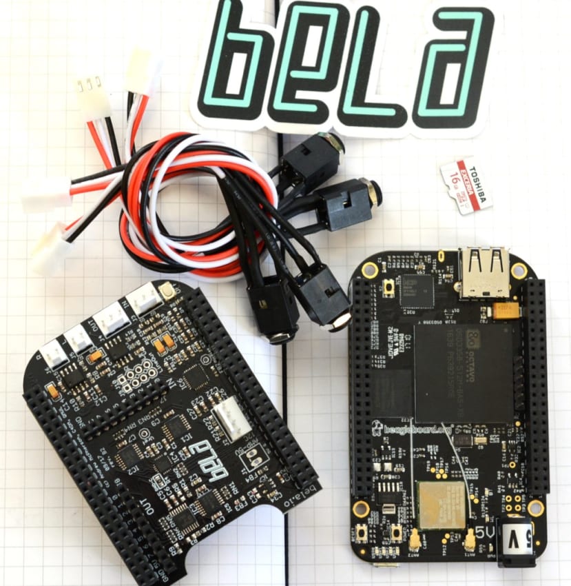
I had heard about the Bela platform, software together with an audio processor “cape” — similar to a Raspberry Pi HAT or Arduino shield, but for the BeagleBone Black development board — and decided to give this a go with a BeagleBone Black Wireless (125-2412) that we had.
Bela was developed at the Queen Mary University of London as a project of the Augmented Instruments Laboratory, who needed a versatile, low latency audio platform for a project they were working on and could not find what they wanted “off the shelf”, so built their own. You can read the story in more detail here.
Getting started
Bela has very useful and comprehensive getting started pages on Github, so that’s where I started.
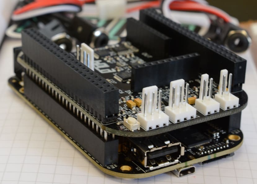
The first job was to fit the Bela cape on to the BeagleBone Black, I could then set up the Bela software. I use Ubuntu for my work computer and Windows in the Red Tin, so I will outline the procedure for both operating systems here.
I downloaded the Bela image from here and un-zipped it. My copy of Ubuntu already had software that un-ziped the .xz format that Bela uses, but if you are using Windows you may need to use something like 7Zip to extract the .img file.
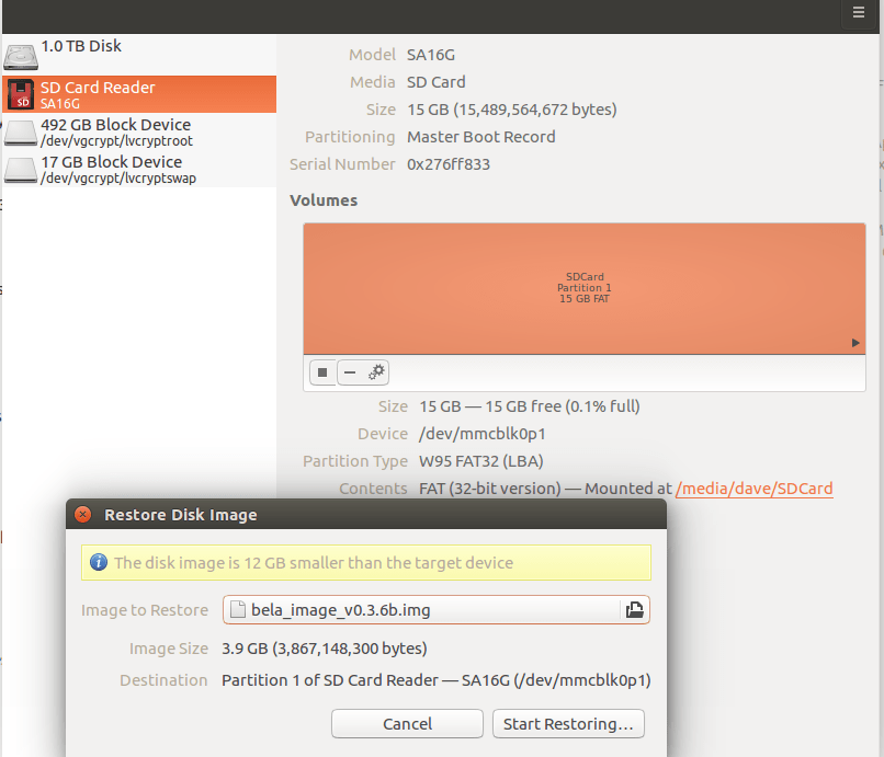
In Ubuntu you can right click the .img file and select “Open with Disk Image Writer”.
Then, making sure you have the SD card selected in the “Destination” menu, click “Start Restoring...”, confirm you really want to do it, enter your password and then just wait for the image to be written to the card. This will erase any existing data on your SD Card!
If you would rather do it from the command line the instructions are on the “Flashing the Bela Image” section of the Bela github pages. If you are using Windows it is recommended to use the Win32 Disk Imager.
Having done the above and inserted the Micro SD Card with the newly written Bela image into its slot on the BeagleBone Black, I connected the Bela/Beaglebone to my computer and waited for it connect. It takes a little while, but the blue flashing LEDs reassuringly indicated stuff was happening. It is then just a case of opening a web browser and going to http://192.168.7.2, the IP address of the BeagleBone Black.
You should then see the Bela IDE in your browser Window. Only what I saw was the Beaglebone page with no sign of Bela. After some investigation I discovered that the BeagleBone Black boots from its built in eMMC memory, which contains a default O/S image. You can force it boot via Micro SD card by powering it down, holding the User button down and then re-connecting it, keeping the button held until the group of 4 LEDs by the Micro USB connector start to show activity.

The little button is quite hard to get at with the Bela cape installed, so it is actually easier to remove it first.
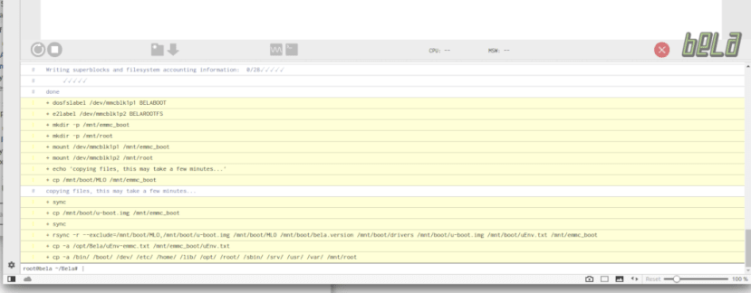
Once I could get into the Bela IDE I could run the following command by entering it into the console section at the bottom of the IDE:
/opt/Bela/bela_flash_emmc.sh
With the Bela image now on the eMMC it would automatically boot from that, so I powered it down, removed the Micro SD and replaced the Bela cape before restarting it. As expected, this time it booted from the Bela image.
The Bela hardware
The Bela cape has a whole load of connectors on it, including:
- Audio Input: 16-bit stereo audio input at 44.1kHz
- Audio Output: 16-bit stereo audio output at 44.1kHz
- Audio power output: 2x 1W 8ohm speaker amplifiers (available when powered from DC jack)
- Analog In: 8x 16-bit analog inputs at 22.05kHz
- Analog Out: 8x 16-bit analog outputs at 22.05kHz
- Digital channels: 16x digital GPIO at 44.1kHz or 88.2kHz
Analogue I/O is also software configurable to give 4 channels at 44.1kHz or 2 channels at 88.1kHz.
The cape comes with cables to connect 3.5mm stereo jack sockets to the audio in and out connectors, which makes life easier.
Trying some examples

I decided the best thing to do now would be to run through some of the examples which can be found on the Examples and Projects page.
This would be a good way to familiarise myself with the Bela IDE and, as I discovered, there were links to the code for all the Examples in the IDE’s menu.
Making it bleep!
#include <Bela.h>
#include <cmath>

float gFrequency = 440.0;
float gPhase;
float gInverseSampleRate;

bool setup(BelaContext *context, void *userData)
{
	gInverseSampleRate = 1.0 / context->audioSampleRate;
	gPhase = 0.0;

	return true;
}

void render(BelaContext *context, void *userData)
{
	for(unsigned int n = 0; n < context->audioFrames; n++) {
		float out = 0.8f * sinf(gPhase);
		gPhase += 2.0f * (float)M_PI * gFrequency * gInverseSampleRate;
		if(gPhase > M_PI)
			gPhase -= 2.0f * (float)M_PI;

		for(unsigned int channel = 0; channel < context->audioOutChannels; channel++) {
			audioWrite(context, n, channel, out);
		}
	}
}

void cleanup(BelaContext *context, void *userData)
{

}


/**
\example sinetone/render.cpp
Producing your first bleep!
---------------------------
This sketch is the hello world of embedded interactive audio. Better known as bleep, it
produces a sine tone.
The frequency of the sine tone is determined by a global variable, `gFrequency`.
The sine tone is produced by incrementing the phase of a sin function
on every audio frame.
In render() you'll see a nested for loop structure. You'll see this in all Bela projects.
The first for loop cycles through 'audioFrames', the second through 'audioChannels' (in this case left 0 and right 1).
It is good to familiarise yourself with this structure as it's fundamental to producing sound with the system.
*/
I started with the sine wave generator. It was simplicity itself to load the code into the Bela IDE and then I just clicked the big green run button. I connected my headphones using the adaptor cable provided and sure enough, I could hear a sine wave.
As you can see in the code above, each of the examples has a comprehensive explanation of what the code is doing as comments at the bottom. As it explains “The frequency of the sine tone is determined by a global variable, `gFrequency` — so having found that variable in the code I could easily alter the value, re-run the code and hear the difference.
LED VU Meter
This one took a little time to assemble. It needed:
- A small breadboard (102-9147)
- 10 x 470ohm resistors (683-3749)
- 7 x green LEDs (228-6004)
- 1 x yellow LED (228-6010)
- 2 x red LEDs (228-5988)
Once I had the components it was straight forward enough to put together and I soon had it wired up and connected to the cape, with the code loaded and running in the IDE. This is when I discovered the LEDs were back to front in the example. I could just swap the yellow and red LEDs with the three green ones at the bottom and turn the whole thing the other way up, but that was going to make the wiring messy, so it was just as easy to reverse the order of the connecting wires and then it worked as expected.
Delay
// Simple Delay on Audio Input with Low Pass Filter

#include <Bela.h>

#define DELAY_BUFFER_SIZE 44100

// Buffer holding previous samples per channel
float gDelayBuffer_l[DELAY_BUFFER_SIZE] = {0};
float gDelayBuffer_r[DELAY_BUFFER_SIZE] = {0};
// Write pointer
int gDelayBufWritePtr = 0;
// Amount of delay
float gDelayAmount = 1.0;
// Amount of feedback
float gDelayFeedbackAmount = 0.999;
// Level of pre-delay input
float gDelayAmountPre = 0.75;
// Amount of delay in samples (needs to be smaller than or equal to the buffer size defined above)
int gDelayInSamples = 22050;

// Butterworth coefficients for low-pass filter @ 8000Hz
float gDel_a0 = 0.1772443606634904;
float gDel_a1 = 0.3544887213269808;
float gDel_a2 = 0.1772443606634904;
float gDel_a3 = -0.5087156198145868;
float gDel_a4 = 0.2176930624685485;

// Previous two input and output values for each channel (required for applying the filter)
float gDel_x1_l = 0;
float gDel_x2_l = 0;
float gDel_y1_l = 0;
float gDel_y2_l = 0;
float gDel_x1_r = 0;
float gDel_x2_r = 0;
float gDel_y1_r = 0;
float gDel_y2_r = 0;

bool setup(BelaContext *context, void *userData)
{

    return true;
}

void render(BelaContext *context, void *userData)
{

    for(unsigned int n = 0; n < context->audioFrames; n++) {

        float out_l = 0;
        float out_r = 0;

        // Read audio inputs
        out_l = audioRead(context,n,0);
        out_r = audioRead(context,n,1);

        // Increment delay buffer write pointer
        if(++gDelayBufWritePtr>DELAY_BUFFER_SIZE)
            gDelayBufWritePtr = 0;

        // Calculate the sample that will be written into the delay buffer...
        // 1. Multiply the current (dry) sample by the pre-delay gain level (set above)
        // 2. Get the previously delayed sample from the buffer, multiply it by the feedback gain and add it to the current sample
        float del_input_l = (gDelayAmountPre * out_l + gDelayBuffer_l[(gDelayBufWritePtr-gDelayInSamples+DELAY_BUFFER_SIZE)%DELAY_BUFFER_SIZE] * gDelayFeedbackAmount);
        float del_input_r = (gDelayAmountPre * out_r + gDelayBuffer_r[(gDelayBufWritePtr-gDelayInSamples+DELAY_BUFFER_SIZE)%DELAY_BUFFER_SIZE] * gDelayFeedbackAmount);

        // ...but let's not write it into the buffer yet! First we need to apply the low-pass filter!

        // Remember these values so that we can update the filter later, as we're about to overwrite it
        float temp_x_l = del_input_l;
        float temp_x_r = del_input_r;

        // Apply the butterworth filter (y = a0*x0 + a1*x1 + a2*x2 + a3*y1 + a4*y2)
        del_input_l = gDel_a0*del_input_l
                    + gDel_a1*gDel_x1_l
                    + gDel_a2*gDel_x2_l
                    + gDel_a3*gDelayBuffer_l[(gDelayBufWritePtr-1+DELAY_BUFFER_SIZE)%DELAY_BUFFER_SIZE]
                    + gDel_a4*gDelayBuffer_l[(gDelayBufWritePtr-2+DELAY_BUFFER_SIZE)%DELAY_BUFFER_SIZE];

        // Update previous values for next iteration of filter processing
        gDel_x2_l = gDel_x1_l;
        gDel_x1_l = temp_x_l;
        gDel_y2_l = gDel_y1_l;
        gDel_y1_l = del_input_l;

        // Repeat process for the right channel
        del_input_r = gDel_a0*del_input_r
                    + gDel_a1*gDel_x1_r
                    + gDel_a2*gDel_x2_r
                    + gDel_a3*gDelayBuffer_r[(gDelayBufWritePtr-1+DELAY_BUFFER_SIZE)%DELAY_BUFFER_SIZE]
                    + gDel_a4*gDelayBuffer_r[(gDelayBufWritePtr-2+DELAY_BUFFER_SIZE)%DELAY_BUFFER_SIZE];

        gDel_x2_r = gDel_x1_r;
        gDel_x1_r = temp_x_r;
        gDel_y2_r = gDel_y1_r;
        gDel_y1_r = del_input_r;

        //  Now we can write it into the delay buffer
        gDelayBuffer_l[gDelayBufWritePtr] = del_input_l;
        gDelayBuffer_r[gDelayBufWritePtr] = del_input_r;

        // Get the delayed sample (by reading `gDelayInSamples` many samples behind our current write pointer) and add it to our output sample
        out_l += gDelayBuffer_l[(gDelayBufWritePtr-gDelayInSamples+DELAY_BUFFER_SIZE)%DELAY_BUFFER_SIZE] * gDelayAmount;
        out_r += gDelayBuffer_r[(gDelayBufWritePtr-gDelayInSamples+DELAY_BUFFER_SIZE)%DELAY_BUFFER_SIZE] * gDelayAmount;

        // Write the sample into the output buffer -- done!
        audioWrite(context, n, 0, out_l);
        audioWrite(context, n, 1, out_r);
    }

}

void cleanup(BelaContext *context, void *userData)
{

}

/**
\example delay/render.cpp
I was now eager to try some of the effects, as my ultimate aim is to use this for an effects module.
As with the other examples, I found the code in the right-hand section of the IDE, listed in the Code Examples Section accessed by clicking the Light Bulb icon.
I thought now would be a good time to learn how to load a sketch on boot, without being connected to a computer, as this would be vital for a standalone effects generator.
First I saved the delay code as a Project by clicking the folder icon in the IDE, cicking the “Save project as” button, calling it “Delay” and clicking Save. Then I could go to “Project Settings” (the Cog Wheel icon), click the drop down next to “Run project on boot” and select my newly saved Delay project. I shut down the BeagleBone and disconnected it from the computer. I then powered it up with a separate power supply and once it had started I could hear the delay in full effect.
Tremelo
The speed of the Tremolo is controlled by a 10K potentiometer (249-9200) that is connected to 3.3V and GND on the cape 1st and 3rd pins, with the 2nd middle pin to analogIn 0.
I ran a sine wave in a loop on my DJ software, to give a clear illustration of how the effect sounds.
Next Steps
My plan now is to build the BeagleBone Black and Bela cap into a module that will fit in the Red Tin, similar to the sound effects module I built. I will also need to work out how to load multiple effects and switch between them with buttons mounted on the case. I know this should be possible, as there are examples of guitar effects boxes built with Bela that do just that.