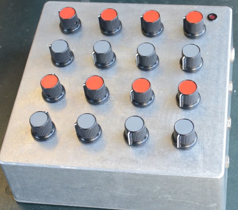
The Red Tin Audio Expander Part 4: Improvements for Reliability and Ease of Maintenance
Follow article
 Dave from DesignSpark
How do you feel about this article? Help us to provide better content for you.
Dave from DesignSpark
Thank you! Your feedback has been received.
Dave from DesignSpark
There was a problem submitting your feedback, please try again later.
Dave from DesignSpark
What do you think of this article?
Replacing the potentiometers, and adding insulation and board-to-cable connectors.
In Part 3 of this series, I outlined how I built the audio op-amps for the matrix mixer on stripboard and fitted them into the enclosure only to then find I only had a single working channel.
After some time spent trying to identify and fix the problems, I decided the only sensible way forward was to take the op-amp circuits back out of the case and then:
- Add some insulation for the boards to help prevent them shorting out when installing:
I have sourced some polypropylene sheet that is just 0.8mm thick, but rigid enough that it will not move about too much. It can also be laser cut and so I can easily make the necessary shapes to shield the circuits and wiring. - Replace the potentiometers with solder versions (016-8178) to make soldering easier and reduce the risk of pins shorting out (I mistakenly thought the pots with the pins would provide a neater option).
- Fit connectors on the circuit boards so that they can be easily removed and re-installed
- Add an indicator LED so I can easily see when the mixer is powered up – a definite oversight on the previous version.
Replacing the potentiometers
The potentiometers I used have nice big lugs for soldering and the metal housing – often referred to as the “can” – meant I could ground the body of the pots as recommended.
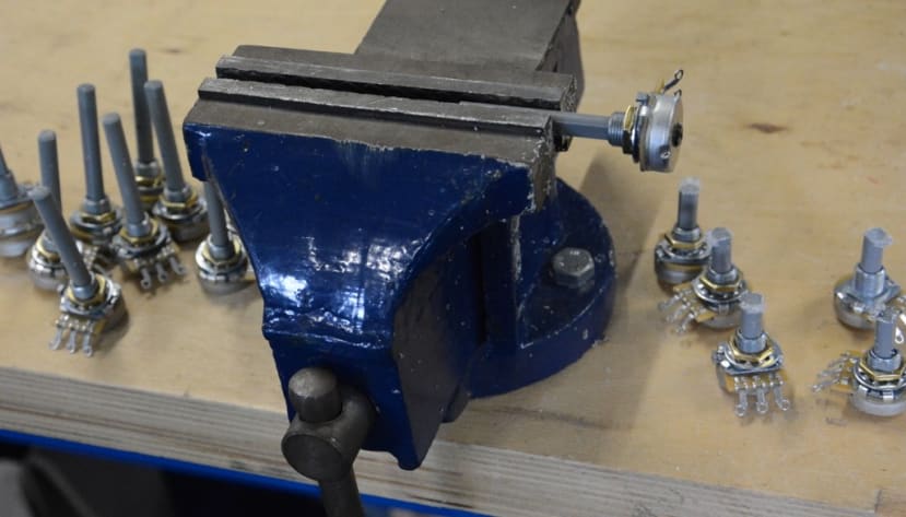
Before I started work on the potentiometers I needed to cut the shafts down to a reasonable length, holding them in a vice while I applied a junior hacksaw.
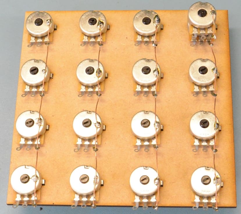
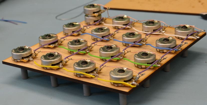
Once again I assembled the potentiometers on a laser-cut piece of MDF. As well as the holes for the shafts, I also cut small holes for the lug that prevents the potentiometer from spinning if it comes loose. Provided the threaded part of the shaft was long enough to go through the top of the enclosure and the 3mm MDF, I could leave the pots attached to it, which would save me either having to drill 16 holes to accommodate the lugs or snap them off so they did not stop the pot from sitting flush with the enclosure. It would also mean the pots would sit firmly in place without danger of spinning around.
Adding headers to the op-amp circuits
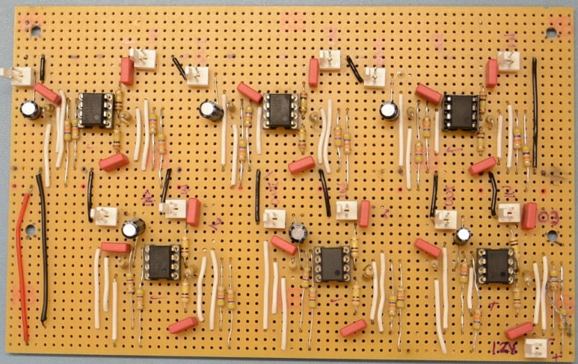
I used Molex KK 254 6410 2-pin headers (483-8461) , double-checking first that the solder pins were the right spacing to fit on the stripboard.
When coupled with the correct plugs
(679-5363)
they feature a locking ramp that would hold the connecting wires firmly in place. This locking mechanism also meant that they could only be connected one way round, so there would be no danger of accidentally reversing the polarity, as long as I made sure I soldered them the right way round in the first place!

I added one socket for each input and output of the op-amps, with another for 12V power and one for the indicator light – labelling them all with permanent marker as I went.
I then made up the cables that would connect the amps to the matrix of potentiometers. Using shielded microphone cable (748-1958) , I crimped terminal contacts (046-7598) onto each wire before inserting them into the plug housing – making sure they were the right way round. I then soldered the other end of the cables to the innards of my enclosure. The inputs from the amps connecting to the input sockets on the enclosure, and the outputs going to the first potentiometer in the corresponding row.
Although I had initially planned for an amp for both input and outputs, I subsequently noticed that on all the schematics for matrix mixers I had seen, amps were only used on the inputs. I decided I would try this and see how it went since it would reduce the complexity of my build and, as I had already soldered up enough op-amp circuits for both inputs and outputs, I could add the necessary connections to amplify the outputs later if needed.
Indicator light
I drilled an 8mm hole in the top of the mixer enclosure to accommodate the LED indicator (700-1978) . I also needed to remove a corner of the MDF sheet that was helping hold the pots in place carefully using a craft knife so the LED would fit flush with the top of the enclosure. Once it was screwed in place I crimped terminal contacts to its wires and fitted a plug housing as I had for the other cables.
Assembling and testing
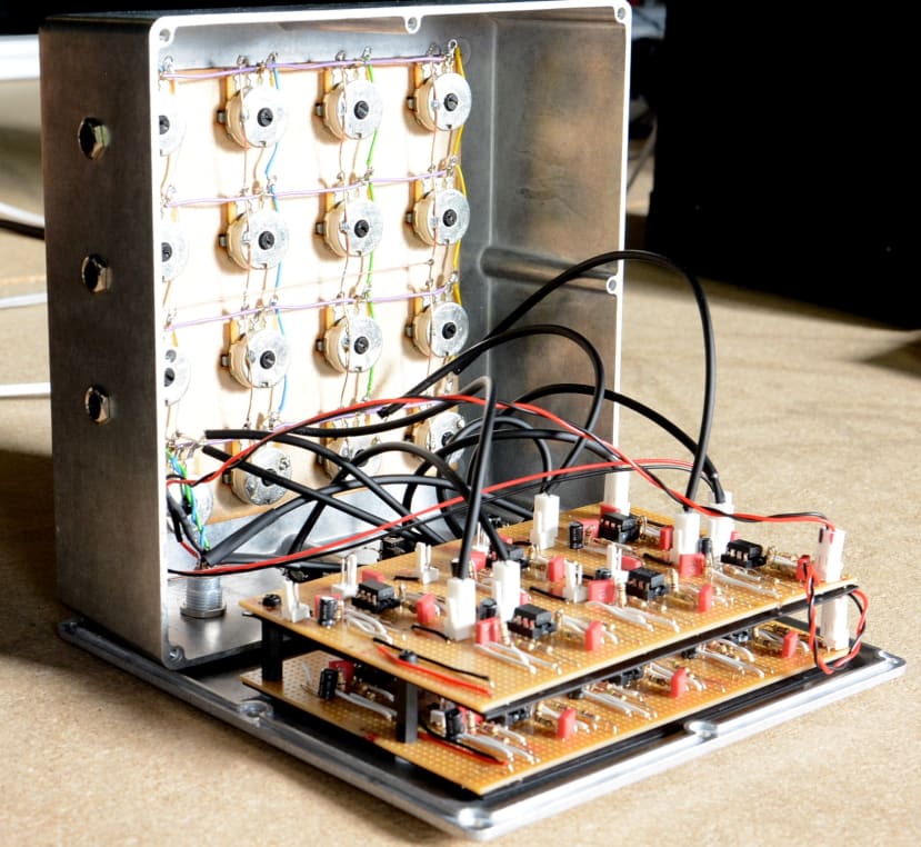
Now it was time to connect everything up and test it.
On the first try, I was hearing some nasty interference in the background but I narrowed this down to a sub-standard power supply. Once I reverted to using the bench supply the noise disappeared, so I needed to test it with the power from the Red Tin.
Once a satisfactory power supply was employed the mixer performed as expected.
It has taken some time and effort to get it to this stage and, I could have saved myself some effort if I had purchased one of the matrix mixer PCBs that are available, but then I would not have learned all the things I have along the way.