The Red Tin Audio Expander Part 3: Stripboard Assembly and Testing
Follow article
 Dave from DesignSpark
How do you feel about this article? Help us to provide better content for you.
Dave from DesignSpark
Thank you! Your feedback has been received.
Dave from DesignSpark
There was a problem submitting your feedback, please try again later.
Dave from DesignSpark
What do you think of this article?
Building the circuit on stripboard, fitting in the enclosure, testing and debugging.

In the previous post, I outlined how I arrived at an op-amp circuit to convert the initial passive prototype into an active mixer. I was going to need 12 of these amps in total for my build.
Transferring to stripboard
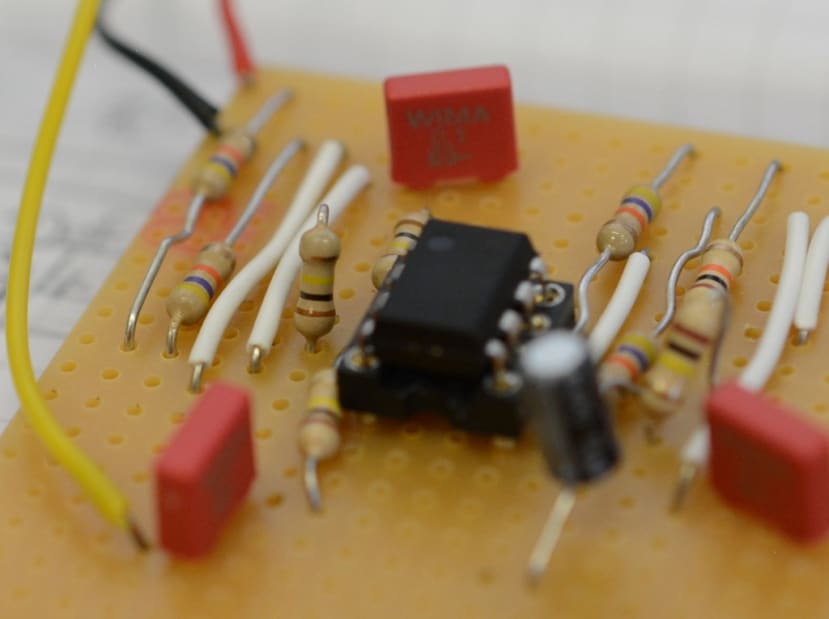
The first job was to transfer the audio op-amp circuit onto a stripboard (100-4328) . I sketched out a rough design in my notebook and then tried the components on the board without soldering, to see how it would fit together and if it would all fit on a single piece of board.
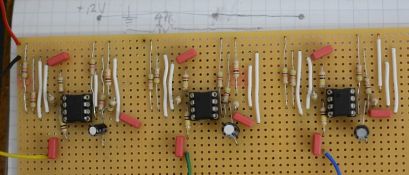
Once I was happy with the arrangement of the components, I started by putting one circuit together on one corner of the stripboard and then tested it. Once I was satisfied it was working OK I then went on to the next one, repeating the process until I had all the amplifier circuits assembled.
A Stereo to Mono Circuit
The addition of one stereo channel added some complication and I needed to do some further research to ascertain the best way to connect the stereo input to the mono channels.
I found an article on that had originally appeared on the Rane website titled “Why not Wye”, that outlined various stereo to mono circuits (Rane make high-end, much sought after DJ mixers and so I reckoned their advice would be good).
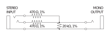
As it says in the article “Here is the rule: Outputs are low impedance and must only be connected to high impedance inputs — never, never tie two outputs directly together — never. If you do, then each output tries to drive the very low impedance of the other, forcing both outputs into current-limit and possible damage. At a minimum severe signal loss”.

I used the example for a stereo to mono box in that document to make my connections and incorporating it into the final circuit, by using two op-amps to provide a stereo input, with the output from both going via the above circuit to provide a mono out.
Having built the audio op-amp circuits I now needed to connect them up to the potentiometers, along with the input and output sockets, and then fit everything into a suitable enclosure
Preparing the enclosure
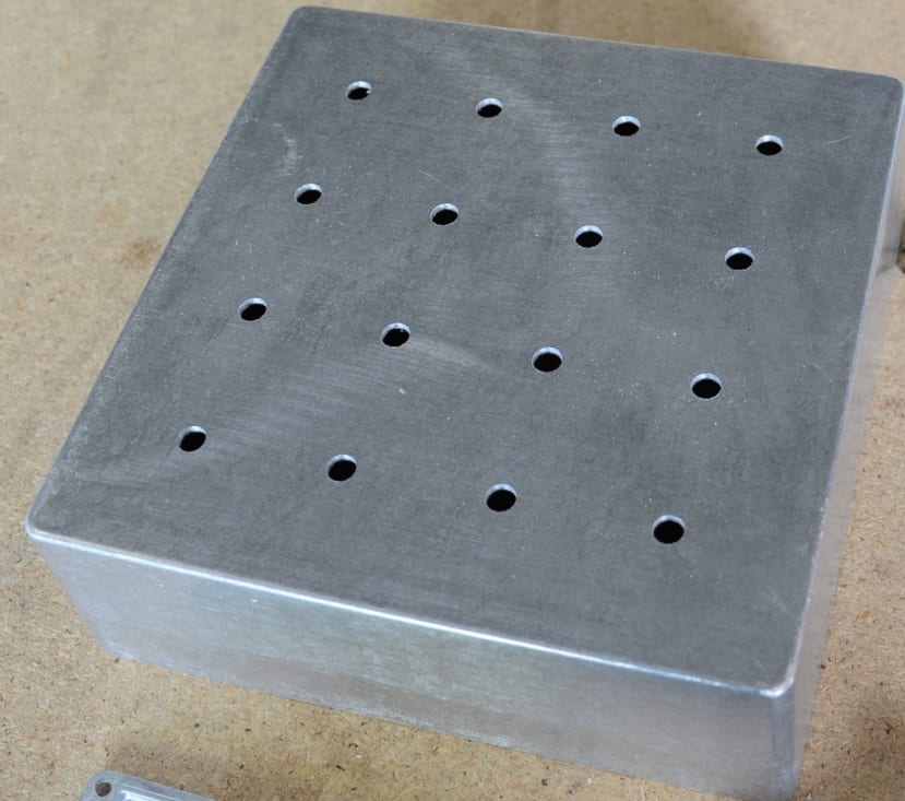
As well as my two circuit boards — which I intended to stack on top of each other separated by spacers and fix to the base — I had 16x potentiometers, 6x 3.5mm jack sockets and an 8-pin Lemo socket to fit.
Laser cutting a template from MDF helped make a neat and accurate job of drilling all the necessary holes.
Materials used are:
- Enclosure (343-9647)
- 15x 100k pots (249-9143)
- 1x 100k double pot (737-7726)
- 6x 3.5mm panel mount jack sockets (913-1015)
- 8-pin Lemo socket (248-4006)
Connecting the potentiometers, inputs, and outputs
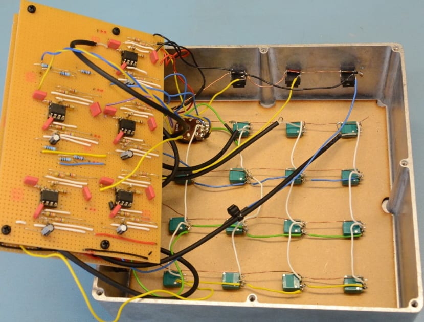
Having drilled the appropriate holes in the enclosure, I fitted the input and output sockets and soldered all the ground pins to a common ground rail, using a piece of copper wire.
I soldered all the potentiometers together on a piece of laser cut MDF that would fit inside the enclosure once the soldering was completed. As I intend to re-do this (see below) I will not go into too much detail here, but I would definitely advise using potentiometers with a larger body and more substantial soldering lugs!
Debugging
Unfortunately, when the mixer was put together I discovered only one input and 2 outputs were working — so I started the process of debugging my build.
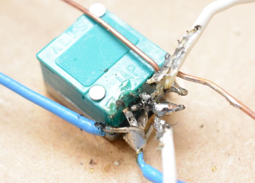
After re-soldering some of my potentiometers several times they were starting to look a bit messy and I was wishing I had bought some with a larger body and soldering tags.
After an hour or two addressing various faults I realised I really needed to overhaul the whole design; fitting the boards into the enclosure was obviously causing some damage and continuously removing them to re-solder things was making things worse.
A cunning plan ...
I decided to take the op-amp circuits back out of the case, labelling the wires to facilitate re-construction, checked they are all working and do any necessary repairs. Then my plan is:

- Add an insulator layer for the boards to help prevent them from shorting out when installed. I have sourced some polypropylene sheet that is just 0.8mm thick but rigid enough that it will not move about too much. It can also be laser cut, so I can easily create the necessary shapes to shield the circuits and wiring.
- Replace the potentiometers with solder lug versions instead of PCB mount, to make soldering these easier and reduce the risk of pins shorting out. I mistakenly thought the pots with the pins would provide a neater option for my mixer.
- Install sockets and plugs on the circuit boards so that they can be easily removed and re-installed. I would also need to clearly label all the wiring.
- I am also going to add an indicator LED so that I can easily see when the mixer is powered up – a definite oversight in this build.
I will detail all this in the next (and hopefully final) installment of this series of posts.