Remap UK - Building a bespoke dog ball launcher: Part 3 (final)
Follow article Dave from DesignSpark
How do you feel about this article? Help us to provide better content for you.
Dave from DesignSpark
Thank you! Your feedback has been received.
Dave from DesignSpark
There was a problem submitting your feedback, please try again later.
Dave from DesignSpark
What do you think of this article?
REMAP is a UK charity which provides bespoke engineered solutions to help people with disabilities to achieve greater independence and quality of life ( Remap.org.uk ). The charity has around 70 local groups across the UK, comprising over 850 volunteer engineers with a variety of skills and disciplines, to design, engineer and produce these bespoke solutions. We help around 4000 people every year, who in many cases are unable to find a suitable solution from NHS or normal commercial sources. This is generally because the need is developed from several different problems, not just the direct issues derived from their disability. All equipment is provided to the beneficiary free of charge, so the charity is reliant on grants and donations to fund materials and equipment.
Solutions range from relatively straightforward carpentry or metalwork to more challenging equipment requirements encompassing electrical, mechanical and control, and 3D printing. In many cases, we are approached by local occupational therapy staff to help people where NHS solutions are not available.
Part 1 of this series of articles discussed the background to a specific case and explained the initial challenges to commence development of the dog ball launcher. Part 2 continued the story of the equipment development and the challenges involved
Our client Olli suffers from muscular dystrophy and spends all his time in his powered wheelchair. He wants to be able to throw a tennis ball for his dog in the garden, but with his health declining significantly over the last year, he is unable to throw or collect a ball. There are devices on the market that will throw balls for dogs, but they all require the ball to be replaced into the machine’s hopper before the ball can be thrown again. Olli bought one of these devices but is now too weak to pick the ball up and drop it in the hopper himself, and so far, he has been unable to train the dog to do it for himself! Olli wants to actively interact with his dog.
Our expert volunteer engineer Noel has been working closely with the client and we continue and conclude his discussion of the equipment design and development, with an initial focus on controlling the launcher operation.
Loading the tennis ball
My new challenge was to decide how to overcome the issues explained in part 2, regarding the power needed to pull the tennis ball past the launch gears before launching the tennis ball.
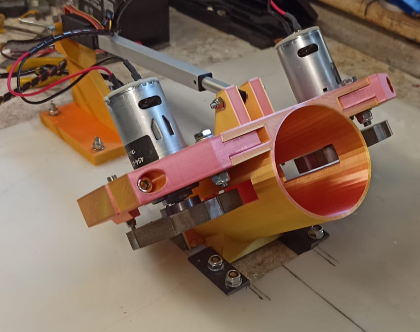
One solution would be to increase the tube gear motors (454-0883) to ones with enough power to pull and squeeze the tennis ball from a standstill. This may require quite a considerable increase in power, weight, etc, which will have knock-on effects with the rest of the design. Another option would be to locate the motors on pivoting mountings that can be moved apart to allow the ball to drop to the bottom of the tube when required. This would require an extra actuator of some sort, but would hopefully not cause such an increase in weight and power drain that increasing the gear motors might do. After some further consideration, I decided to go for the second option of designing and building pivoting tube gear mountings. This arrangement used actuators (918-1338) available from RS components.
Here are the two new support arms in place, with the actuator. The movement is not large as there is only a 15mm squeeze on the ball to relax.

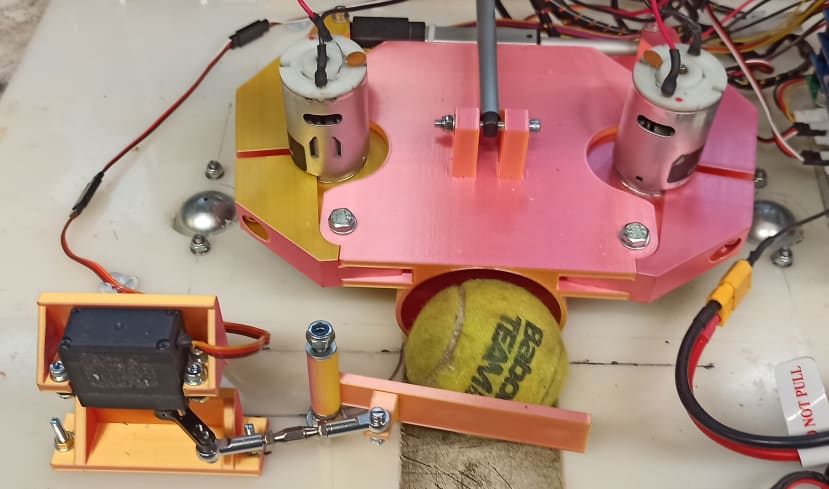
Next, I wanted to mount a servo on the end of the tube which would act as a lever to push the tennis ball into the rotating gears. I needed a special mount so set about modelling one on CAD, together with an extended lever (or horn) on the servo’s arm.

You can see the servo on its mounting on the bottom of the tube.
Testing
The system was now in a position to carry out some testing to see if the moving arms and trigger worked. I modified the Arduino (715-4084) program to carry out a sequence of events once the “fire” button on the RC transmitter was pressed.
I carried out several tests with a tennis ball at all launch speeds. The ball launched well at slow and medium speeds, but for a high-speed launch, the ball was not pulled into the gears. Instead, the gears simply skidded on the surface of the ball without grabbing it. It appeared that there was not enough friction to pull the ball through against the force needed to squeeze it.
After a bit of thought, I decided to machine some angled grooves into the circumference of the gears so that they stood a better chance of grabbing the ball when running at high speed.
With the extra grooves machined, I carried out some more tests, but sadly it made no real difference. The gears continued to skid on the surface of the ball when at high speed.
I have a few options now to try and overcome this problem. I could carry out more tests to see at what gear speed the ball still just launched, and then use this for the “max launch speed” setting. This might work, but it might be intermittent. I had noticed that with our own dog’s tennis balls, they progressively get harder to squeeze the older they get, and the longer the dog had chewed them. Consequently, they may be okay one day, but on another day, they would be just too hard to be squeezed between the gears.
I could consider increasing the power of the trigger to increase the force used to push the ball into the gears. I wasn’t sure this would work, but was also concerned about how I would fit a larger servo/actuator.
Another option will be to try and change the sequence of events during the launch procedure as follows:
- The assumption will be made that the ball is at the bottom of the tube because the tube will be inclined before launch.
- The trigger will be operated to lift the ball to between the gears, but with the gears in their “apart” position, the ball will not be launched yet.
- The gear motors are run up to the required speed.
- The motor mounts are moved to their “together” position. At some point during the movement of the arms, the gears will pick up the ball, squeeze it, and hopefully launch it.
- Once the ball has been launched, the trigger servo will be released, the gear motors brought to rest, and the motor mounts moved to their “apart” position.
Modifications
As well as trying to fix the launch issues, I wanted to work on mounting the tube to the “base” of the ball launch vehicle so that I could carry out more tests on the tube angle actuator. I needed a rear actuator mount for the tube actuator so started to model one on CAD.
Having printed it, I wondered if I was going to have issues with scooping the ball into the launch tube, because I now realise that I will probably need the front of the tube to almost rest on the floor when the ball is being scooped up. With this rear actuator mounting bracket, I wasn’t sure if it had enough height and clearance for the angle of the actuator. More tests and adjustments are needed over the next few days I think!
After a bit of filing and fettling, I managed to get the hinge fitted with enough space for it to tilt the tube up at an angle of about 60 degrees.
The next items to fit to the base were the wheels. I received a couple of 84mm diameter wheels (399-5204) from RS Components. Then, I had to support the motors somehow. Below you can see the complete drive assemblies in place.

It was now time to add the driving functionality to the Arduino software. The two new items of code were to provide the “spinning” function from the left joystick’s horizontal movement, and the single driving and steering function from the right-hand joystick.
After correcting a typo in my software, the ball launcher now spat the ball out happily at full speed! This meant I could now return to the original sequence of operation when launching the ball. I could now bring the gears together completely before spinning them up, and then pushing the ball between them. Having to use the alternative of pushing the ball between the spinning gears while moving them together was prone to inconsistent ball launching.
Further testing
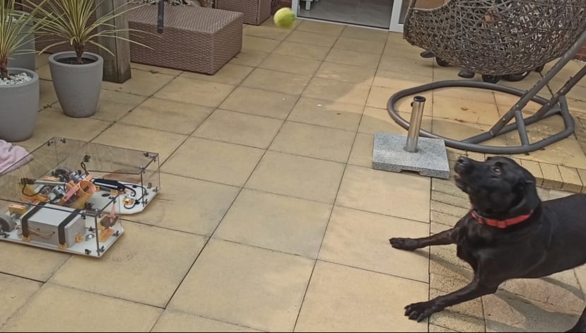
The project was now at a stage when I felt it would be good to test the launcher in Olli’s garden, just to make sure it would handle any undulations, cracks, or gaps in the paved floor.
Olli’s garden had varying slabs, and some mild inclines, but luckily the launcher managed them without “beaching itself” on any. We also tried the launcher out on Olli’s Labrador, Ted. Once Ted had heard the gears spinning up and seen the ball subsequently launched out from the tube, he eagerly awaited the ball each time he heard the gears subsequently spinning up. This was good as it confirmed he would be interested in playing with the launcher once it was complete.
After the successful tests of the launcher in Olli’s garden, it was time to work on the mandible arms that would scoop the tennis ball back into the tube. I had planned to fix a couple of metal posts in front and to the side of the tube, on which a couple of mandible arms would pivot.
Here you can see one arm pushing the ball into the tube. The ball still sometimes snagged on the side of the gutter in the baseplate and caused the arm to bend as the arm moved. The arm made some alarming creaking noises but seemed to stay in one piece. I felt it was only a matter of time before the arm or mounting would suffer catastrophic failure, so looked for some way of cushioning the arm.
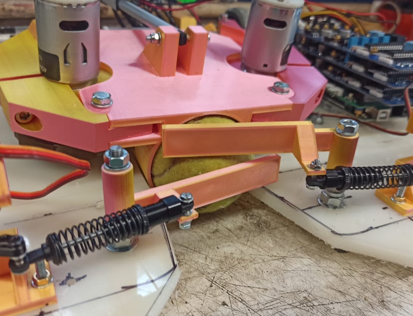
I came across these RC suspension units and decided to replace the fixed linkages between the arms and servos with these.
Here you can see both arms in place, each now with a sprung loaded link.
There was still a problem, however. I was modelling the scooping arms on the robotic ball launcher Olli had identified, which had two arms to scoop the ball up. However, the robot used small and smooth balls which slide easily against the arms. In our launcher, the ball was rough with a cloth surface, and would often get stuck on the underside of the upper arm as it was being pushed up into the tube. After some experimenting, I found the scooping was much more reliable with a single arm rather than two. I felt it best to abandon the second upper mandible arm but increase the size of the lower arm to compensate. This way, as the tube was raised, the ball would be prevented from possibly rolling out again.
Here is a view of the new arm in situ. It seems to do its job well and stopped the ball rolling out of the tube as it was raised.

One thing that was nagging me was the tube not always being low enough for the ball to roll into it freely from rough ground. I felt it needed to be lowered just a fraction more, but the outside circumference stopped it.
I came up with a few modifications, the main one being an angled slice through the top rim of the tube so that it could be lowered even closer to the ground.
During some further tests, I noticed that driving wheels would sometimes skid on the ground if the terrain was a bit rough. The problem could be that with a four “point of contact” configuration where there are two wheels and two roller balls, that on uneven ground, the weight on the wheels would vary and be so light that occasionally the wheels could spin.
The launcher was now getting to the stage where I needed to enclose and secure many of the electronics, rather than have them “blue tacked” to the base plate. I took a close look at the base of the controller “brick”, and the inside of the ABS box (201-0190) , and felt that if I could create some form of base plate that would fix to the Arduino mounting holes, I could shape the plate so that it would fit neatly around all the mounting lugs in the box, and stop everything from sliding around. There were lots of cutouts, but these would ensure the plate would fit evenly on the bottom of the box.
The wiring was one of the next jobs to sort out. I hadn’t made any attempts to use the correct length of wires or to identify which cables went where, so now I set about cutting the wires to the correct lengths and putting coloured cable ties on the ends.

In the picture, you can see the various wires now being fed through grommets on the side of the box to the PCBs, and on the ends next to the connectors, there are coloured ties.
Once all the cables were colour-coded and cut to length, I cut a rectangle of foam from a yoga mat, as this type of foam was ideal for cushioning the PCB cards in the box. The foam was about 10mm thick and was the ideal size to pad out the space between the underside of the lid and the top of the PCBs.
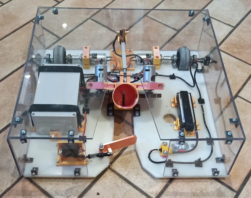
The final task was to fix the clear polycarbonate covers (068-1659) to the launcher. I had received a large sheet from DesignSpark so set about cutting it into suitable-sized pieces.
Using clear plastic has the added advantage that if you are behind the launcher, you can still see the ball so you can guide it into the launch tube easily. If it was not transparent, you would have a harder job.

It was now time to arrange a convenient time and day to meet up with Olli and drop the launcher off with him to try out. Luckily the weather was good when I arrived, and it only took Ted, Olli’s dog, a few launches to figure out what was going on. I recorded a couple of minutes of video of them using the launcher and then left them to it to give me feedback over the coming days and weeks.
Hopefully, things will continue to work okay, but if things do shake loose, break, or need adjusting, it won’t be for a while yet.

Teething problems
After a period of using the launcher, Olli reported a few issues.
- One of the drive couplings appeared to be slipping Although the spec of the coupling I had used stated that there were two grub screws on each end, offset by 120 degrees, the ones supplied only had one grub screw. I looked for some other couplings that might be better and found some with a clamp type of arrangement rather than a grub screw. I felt that a clamp arrangement would provide more friction between the motor shaft and the coupling, provided it was a tight fit. I ordered some of these from RS, as well as some couplings with two grub screws at each end.
- The battery connection was a bit awkward to use. It was horizontal and difficult to reach behind the polycarbonate panels. It wasn’t a showstopper, but would be better if it was vertical. I decided to make an adapter out of an angle iron bar that would change the angle of the clamp holding the connector.
- This one was a bit unexpected! After using the launcher for a while with Ted the dog returning the ball back for another throw, the ball would increasingly get more and more slimy. This meant that the ball could not be thrown quite as far because the gears would not get the same purchase on the slimy balls. In turn, Ted wouldn’t have to run after balls, but could just sit in front of the launcher and catch them in his mouth as they came out. Changing the ball for a new dry one was not popular with Ted, as he liked to stick with the original ball, no matter how slimy, and would lose interest if the ball was changed. This meant I had to figure out how to increase the purchase on the ball.
After considering a few options like increasing the battery voltage, or changing the motors for higher speed ones, I decided to go for another 5mm of squeeze on the ball. This meant modifying the position of the motors on the hinges and then printing off some new ones. It also would mean that the hinges might have to be withdrawn a bit further to allow the ball to travel passed the gears after they were scooped up. This in turn would need a small change to the end stops, and the software driving the actuator.
I paid a visit to Olli to carry out the three planned changes. After further testing, adjustments and software mods were done back at home.
Once back home, I was able to undo the spinning wheels and swap the motor hinges out. However, it then became apparent that the increase of 5mm of squeeze was too much. Firstly, the actuator didn’t have enough extension to move the hinges far enough apart to allow the ball to roll past the gears. Additionally, when the gears were brought together, they were just starting to touch the ball at the bottom of the tube, which would prevent them from spinning up to speed when required. All in all, it looked like 5mm of extra squeeze was too ambitious, and I need to aim for a smaller increase. I opted for an extra 2mm of squeeze, which meant going back to CAD and adjusting the hinge dimensions again.
Final Solution
I printed two new hinges and fitted them to the motors. The actuator was just able to move the hinges far enough apart so that the ball could roll past the gears. The gear also (just) had enough space once the gears were brought together and sped up to speed. This resulted in there being no problem with the balls being launched, so it was now a case of handing the launcher back to Olli and Ted, and letting them get more testing/playing underway!
Olli and Ted have since spent several long sessions using the launcher, only being curtailed when the battery finally went flat after 90 minutes of use, or when the weather was too cold to remain outdoors!
Some video links of the launcher in use are given below
Remap is pleased to help people with disabilities to have a better quality of life such as Olli has done in his relationship with his dog Ted. At the same time our volunteers like Noel who have skills to put to good use gain their own reward in seeing the pleasure gained by others from their good work.
Thanks also to DesignSpark for supporting the charity in the selection and provision of a number of components for this equipment.
Below are videos taken during the completion of this project.
Explanation of finished dog ball launcher:
Demonstration of how the tennis ball is scooped up:
The sequence of events during the ball launch:
Tests with Olli’s own dog, Ted:
Comments