Remap UK - Building a bespoke dog ball launcher: Part 2
Follow article Dave from DesignSpark
How do you feel about this article? Help us to provide better content for you.
Dave from DesignSpark
Thank you! Your feedback has been received.
Dave from DesignSpark
There was a problem submitting your feedback, please try again later.
Dave from DesignSpark
What do you think of this article?
Remap is a UK charity which provides bespoke engineered solutions to help people with disabilities to achieve greater independence and quality of life ( Remap.org.uk ). The charity has around 70 local groups across the UK, comprising over 850 volunteer engineers with a variety of skills and disciplines, to design, engineer and produce these bespoke solutions. We help around 4000 people every year, who in many cases are unable to find a suitable solution from NHS or from normal commercial sources. This is generally because the need is developed from a number of different problems, not just the direct issues derived from their disability. All equipment is provided to the beneficiary free of charge, so the charity is reliant on grants and donations to fund materials and equipment.
Solutions range from relatively straightforward carpentry or metalwork to more challenging equipment requirements encompassing electrical, mechanical and control, and 3D printing. For many cases, we are approached by local occupational therapy staff to help people where NHS solutions are not available.
Part 1 of this series of articles discussed the background to a specific case and explained the initial challenges to commence development of the dog ball launcher
Our client Olli suffers from muscular dystrophy and spends all his time in his powered wheelchair. He wants to be able to throw a tennis ball for his dog in the garden, but with his health declining significantly over the last year, he is unable to throw or collect a ball. There are devices on the market that will throw balls for dogs, but they all require the ball to be replaced into the machine’s hopper before the ball can be thrown again. Olli bought one of these devices but is now too weak to pick the ball up and drop it in the hopper himself, and so far, he has been unable to train the dog to do it for himself! Olli wants to actively interact with his dog.
Our expert volunteer engineer Noel has been working closely with the client and we continue his discussion of the equipment design and development, with an initial focus on controlling the launcher operation.
I decided to investigate how I would get the Arduino to decode the RC receiver’s SBUS data stream. I had an Arduino, and a logic analyser so wired them together and connected them to my PC. With this combination of devices, I could see the SBUS data stream on the logic analyser while also being able to decode and display the values on the Arduino.

Here is a view of the SBUS data stream. It’s a 100,000-baud data stream of 8 data bits, even parity, and 2 stop bits. The steam contains 25 x 8-bit bytes which are then mapped to the 18 radio channels. Each radio channel is 11 bits long, so it’s not obvious by looking at the raw data stream to see what each channel’s value is. This is where the Arduino library routine comes into play, to take all the effort out of decoding the 18 channels.
From the stream above you can see the hex data header of “0x0f” on the left, and the data footer of “0x00” on the right. This data stream is about 3mSec in length and repeats every 14mSec. All data from the 18 channels sit between the header and foot bytes. Seeing this stream on the logic analyser gave me confidence that the source was okay, and it was now a job to write a short routine to test whether the Arduino was able to correctly decode and display the 18 channels ok.
One peculiarity of the SBUS data stream is that it is the inverse of a regular serial data stream. E.g. when there is no data, the signal level is normally held high. On the SBUS data stream, the signal is held low when no data is present. You can see this on the left-hand side of the logic analyser trace above. Because the Arduino will be using one of its in-build serial port devices, it will not easily read the raw SBUS data stream. I will therefore have to invert the signal using a transistor so that the data stream presented to the serial port’s UART device can be decoded correctly.

Above you can see the RC receiver connected to the Arduino. The transistor inverter is top right and consists of a MOSFET and two resistors. With this arrangement, I wrote a simple Arduino program and confirmed I could see all the channels in the SBUS data stream.
I needed to also work out which controller channels I would use, and which functions they would perform. The controller with its conventional control usage for aeroplanes is shown below.

However, I intend to use the controls as follows, which may need a bit of explaining.
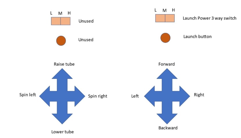
Raising and lowering the launch tube
We could use the throttle stick in proportional mode such that the elevation of the tube is proportional to the position of the stick. Alternatively, we can use the throttle stick in increment mode to raise or lower the tube. With the stick in the middle position, the tube remains where it currently is. If the stick is moved upwards, then the tube is raised, and if the stick is moved downwards, then the tube is lowered. If we want to use the stick in proportional mode, then it would make sense to not fit the optional return spring to the controller. On the other hand, if we want to use the stick in incremental mode, then it would make sense to fit the return spring. My personal opinion is that the incremental mode would be easier to use. Olli agreed that this was probably the best option.
A point I needed to bear in mind was that in proportional mode, it would be necessary to have some form of position sensor on the tube so that its position can be matched with the stick’s position. I’m considering using a linear actuator to raise and lower the tube, which comes in two types. One with a position sensor, and the other without a position sensor. The units with the position sensor are considerably more expensive than the other type. Although having the position sensor can be useful, it is not essential as they have limit switches that electrically disconnect the motors if they reach the end stops. The lack of current being drawn can be used to establish if the motor is at the end of its track. The decision of which actuator to choose may be dependent on whether DesignSpark agrees to sponsor this project or not.
I’ve been considering not having a control specifically for the “mandible” arms that scoop the ball into the tube. My intention is that when the launch tube is lowered to its lowest position, the arms will automatically open. You can then “chase” the ball and get it into position in front of the tube before operating the “raise tube” stick. This will close the arms, and then continue to raise the tube.
Skid steering with forward/backward and left/right stick
The ball launcher will have two wheels at the rear of the unit and a caster wheel (or similar) in the centre at the front. The rear wheels will drive the unit and will control the direction using skid steering. E.g one wheel will rotate faster than the other in order to steer. I propose to use the righthand stick to skid steer the launcher. The speed will be proportional to the stick’s position.
Spin left and spin right
Spinning the launcher gives much finer control than skid steering. When spinning, one wheel rotates in one direction while the other wheel goes in the opposite direction, which allows the launcher to rotate on the spot. I am proposing to use the left-hand stick rudder control to perform this function. The spin stick will override the control of the skid steer stick. In other words, if the launcher is already moving, but the spin stick is moved, the skid steer stick will be ignored, and the wheels will be solely controlled by the spin stick.
Launch button and launch power switch
There is a three-way rocker switch on the controller that I intend to use to set the power (or throwing range) of the launcher. Effectively it will determine the speed the launch gears will spin at; either slowly, medium, or fast.
The launch button will initiate the launch sequence! Once pressed, the launch gears will rotate slowly for a short period to move the ball beyond the gears and into the bottom of the tube. The gears will then stop and run up in the forward direction according to the “launch power” switch. Once up to speed, the trigger will be activated that raises the ball into the gears where it will hopefully be shot out of the tube.
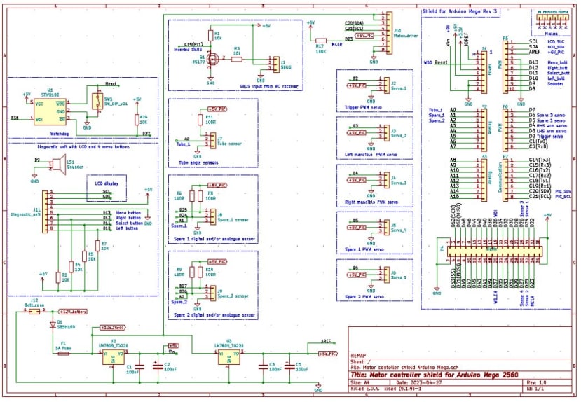
Interfaces between the Arduino and the ball launcher components.
I already had an Arduino “Shield board” that I had used on a previous project, so modified this to suit the requirements of the ball launcher. I used an open-source program which allows you to create a schematic diagram, and then use this to layout the components on a PCB.
Having charged the Lipo 3S battery, I noticed that when fully charged, its terminal voltage was 12.6v, not 11.1v. Not quite sure why this might be, but the Shield board should be able to handle this okay.
The “Shield board” will take in 12.6v from the Lipo 3S battery, and will provide a 9v feed for the Arduino, and a 5v feed for the sensor circuits and motor controller boards. It will also feed the full 12.6v through to the drive motors and tube actuator. I made provision for five PWM servos outputs,
one SBUS radio data stream input, one analogue position sensor input for the tube actuator, and a couple of spare digital/analogue inputs should they be needed.
Once the schematic was drawn, it was then a case of using this to lay out the board in preparation for generating the relevant Gerber files for manufacturing.
Here is KiCad’s visualisation of what the board might look like once it is manufactured and populated.
For the wheel driving motors, ball launching gear motors, and tube raising actuator, I was proposing to use the motor controller I had used on a previous project. You can stack as many of these as required onto the Arduino Shield board, so I felt this was a good solution to adopt here.
Here is a visualisation of what the board might look like once it is manufactured and populated.

Having generated all the Gerber files necessary for the Shield and Motor Controller boards, I sent them off to a PCB supplier and received them shortly afterwards.

The blue boards on the left are the motor controller boards, which are capable of controlling two separate motors each. The green boards on the right are the “shield” boards that allow the radio receiver, motor position sensors, and PWM servos to be controlled by the Arduino.
I will need three blue boards to control five motors, and one green board to interface to the Arduino. I had to order the minimum of five of each board, but at least I will have a few spares should they be needed.
Developing the launch tube
Before printing my first attempt at the launch tube, I needed to do some maths on the positioning of the spinning gears. There were some parameters to be set before working out where to position the motors on the tube. I had previously established the diameter of the gears, so that was one parameter set, but I also needed to set the distance between the gears through which the tennis ball would be grabbed. Effectively I needed to set the distance I wanted the ball to be squashed as it passed between the gears. The more it squashed the ball, the longer the gears would be in contact with the ball and the longer it would have to accelerate the ball from rest to its final velocity. If I squashed the ball too much, then it might not be grabbed by the gears, so there was a trade-off to be made. Also, I wanted to know how far the ball had to be pushed when at the bottom of the tube, for it to be grabbed by the gears.
With all these parameters in mind, I created a spreadsheet where I could change them and see the resulting changes in motor positions.
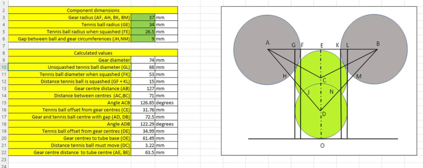
After having selected the parameters I thought were about right, I printed the first prototype on my 3D printer.

Testing the Launcher
After some initial trials assessing the amount of “squeeze” needed on the tennis balls, with varying success of launch distance, it was back to the spreadsheet once more with the ball now being squeezed by 15mm, then made the changes before printing the tube out again, this time in black.

This time when the motors were spun up to speed, and the tube shook to lift the ball into the gears, the ball shot out of the tube across the garage, and into the garage doors. The extra 5mm of squeeze had had the desired effect, but the garage was obviously too small a testing ground now, so I completed the tests outdoors using my dog as a testing agent. Success !!
Here is a link for the first video of testing with our dog. It only shows the launch tube – nothing else is yet built!
This is the link to the second test where the tube can be raised and lowered.
After a couple of days in the garage with a soldering iron, I had one “shield”, and three “motor controller” cards built, and developed the brick assembly, fitted to the Arduino board

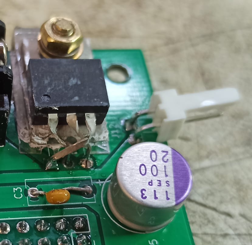
I started to carry out a few tests on the hardware by connecting a couple of servos, and a linear actuator to the brick. With a few lines of code to allow the radio transmitter to move the motors around, I was able to confirm that the cards were functioning ok. However, after a few minutes of constant operation of the servos, I noticed that the LEDs on the motor controller cards started to flicker, and one of the servos stopped moving completely. On further investigation, I noticed that the 5v regulator that provides power to the motor controller cards and servos was getting quite hot. A wet finger on the device didn’t sizzle, but it was too hot to touch. I checked the datasheets for this particular device and found that its maximum current output was 0.5 amps. It seems that when all the devices connected to this 5v supply were being worked continuously, the regulator started to overheat. I did some research and identified a 5v regulator that could provide 3 amps, so decided to order a new device and swap them over. I also decided to fit an aluminium heat sink to the regulator to stop it getting too hot.
One problem I hadn’t foreseen when changing the regulator was that the pinouts of the new regulator were different to the original one. The device shapes were the same, but the pinout was different to the conventional regulator layout. The normal process would be to modify the circuit board layout and have new ones built.
I felt this was a bit excessive and would cause delays and extra expense, so I decided to simply bend the device's leads so that it fitted the existing footprint. It was a bit fiddly, but I managed it okay.
Loading the tennis ball
I was now in a position to test a few features to see if my initial concept of loading the tennis ball once it had been scooped up, was going to be possible. I hoped that once the ball had been scooped up into the tube, I could reverse the tube gear motors to pull the ball down past the gears and into the bottom of the tube. However, with the tennis ball being squashed by 15mm as it passed between the gears, the motors did not have the power to pull the ball through from standstill. They simply grabbed the ball, but then stopped after very lightly squeezing the ball. During my previous tests to fire the ball out of the tube, I was able to get the motors up to full speed before introducing the ball between them. The momentum of the steel gears was enough to overcome any squeezing resistance offered by the ball.
The challenge now was to decide how to overcome this issue!
This will be discussed in the next article together with the development of the ball scoop collection arrangement.
The current status of the launcher is nicely summarised in the video below.