Microcontroller Interfaces: RC Servos
Follow article
 Dave from DesignSpark
How do you feel about this article? Help us to provide better content for you.
Dave from DesignSpark
Thank you! Your feedback has been received.
Dave from DesignSpark
There was a problem submitting your feedback, please try again later.
Dave from DesignSpark
What do you think of this article?
The RC Servo or Hobby Servo has been used to move the control surfaces of Radio-Control (RC) model aircraft for many years. It has since become very popular for driving the limb joints of small humanoid robots, and when converted for continuous rotation, the wheels of mobile robots. However, some features optimal for aircraft control are less than ideal for robots. First, let’s get the terminology straight:
- The term Servo is short for Servomechanism, a device which uses internal feedback to ensure that its mechanical output follows an input control setting. That’s what I’m talking about here.
- A servo motor is the source of motion in a servomechanism, in this case a small PMDC motor.
- A Servomotor is usually a PMDC motor optimised for use in a servomechanism, perhaps featuring rapid acceleration and built-in feedback sensors. They tend to cost a lot of money and are definitely not found in hobby servos!
These definitions are important, particularly when searching for suitable devices on the Internet. Use the search term ‘rc servo’.
Position-Control Servo
This type of servo has a rotary output, but the shaft can only rotate a maximum of half a turn or 180°. With a lever called a ‘horn’ attached to the output shaft it can provide a linear push-pull action, hence its original purpose as an actuator for the flight controls of a model aircraft. Outwardly, all hobby servos look the same: a rectangular plastic or alloy box with two sets of fixing lugs, a 3-wire flat cable connection with 0.1in pitch socket header, and a splined output shaft protruding from one side.
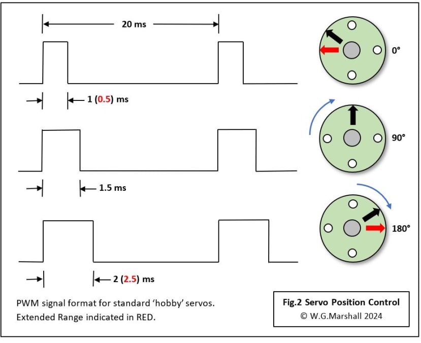
All ‘analogue’ servos are controlled in the same way: angular position is encoded in a constant repetition rate (50Hz) pulse train where the width of a pulse carries the information. It’s known as Pulse Width Modulation or PWM. A pulse width of 1ms corresponds to maximum anticlockwise while 2ms turns the servo to the maximum clockwise position. It’s often assumed that a servo will turn through 180° with these numbers, but that is usually not the case (see later).
Inside an RC Servo
All RC servos have the same basic internal format (Fig.1): a box containing a DC motor, a compact reduction geartrain and a circuit board.
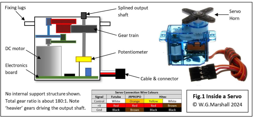
This is usually incredibly weedy and cheap-looking because it must fit into the case with a whole lot of other components. Fortunately, the gearbox which is necessary to reduce its rotational speed from about 6000rpm to an output in the region of 30rpm, multiplies the torque available by the same factor.
The Geartrain
A lot of gears are crammed in to achieve a reduction factor of about 180:1. Of course, the output shaft cannot rotate more than half a turn, so datasheets normally describe servo speed in terms of how long it takes to turn by 60°. For example, a typical figure might be 0.15 secs/60°. That rapid movement could be a problem when using servos to drive the joints of a legged robot. It does tend to make it lurch about like a mechanical toy but is easily solved by ensuring that movement from one angle to another doesn’t take place in one go. Instead, incremental changes in the PWM signal are made, each separated by a short delay until the target angle is reached.
Torque
All RC servos will deliver an impressive amount of torque thanks to the gears - even the Minis and Micros. A standard ‘power’ servo can have a torque figure of around 170N.cm measured at a distance of 1cm along the servo horn. That means, in theory, the servo can hold a weight of over 17kg hanging 1cm along the horn. In practice, a basic low-cost servo with nylon gears and no proper shaft bearings is unlikely to last very long if asked repeatedly to apply its theoretical maximum torque. Load up a servo too heavily and you will soon hear the crunching sound of stripping gear teeth. For robust applications, servo manufacturers make more expensive versions of their products with metal (brass) gears and ball-bearings on the output shaft. Metal gears certainly won’t break easily, but they will wear, ultimately rendering the servo inaccurate due to all the ‘slop’ in the geartrain. They also add to the overall weight, and the increase in geartrain inertia slows the servo’s response to a change. Nylon gears might break if mistreated, but wear is negligible. Servos with gears made from an enhanced plastic formulation called Karbonite are now available offering light weight, high-strength and long-life – at a price.
For a robot project, it’s very important to select servos with a good margin of torque. I have a toy/educational robot arm driven by micro-servos that’s prone to emitting loud buzzing noises and thrashing about wildly. I’m pretty sure the motors are not up to the task, load-wise.
The Electronics
It’s the electronics that turns a motor-gearbox set into a servomechanism with an operating principle based on feedback control. A potentiometer turned by the output shaft sets the pulse duration of a monostable triggered by the input control pulse. The two pulses are compared and the difference in duration between them provides an error signal to the motor driver circuit. The longer the error pulse, the faster the motor turns, slowing down as the error shrinks until it stops when the error reaches zero. Actually, the motor drive is cut off when a certain minimum error pulse width is achieved, introducing a short ‘deadband’ zone around the target position. The deadband stops the motor jittering once it has stopped, assuming any load has been removed. It must be remembered that with this type of servo, there is no ‘holding force’ applied once the target angle is reached.
Until recently, the circuits in an RC servo were always analogue; digital servos are available now with a microcontroller doing most of the processing. Going digital improves speed and accuracy by working with a higher PWM frequency: 300Hz, up from the original 50Hz. Digital servos are also faster to react because the microcontroller can drive the motor at high-speed right to the target angle, rather than ramping down to a stop. The downside is a potential drop in reliability by having a complex digital chip right next to a major source of electrical interference: a PMDC motor!
Servo Interface
The format of the control signal which determines the servo position is shown in Fig.2. It may seem over-complicated; why not after all, just use a variable voltage? What we have here is a method of encoding data called Pulse Width Modulation (PWM) used to modulate a Radio Frequency (RF) carrier for a wireless communications link. It all comes back to the original application for the hobby servo – radio-controlled model aircraft. Perhaps confusingly, PMDC motors can be driven directly by a PWM format signal with the pulse-width determining the motor speed.
Earlier I suggested that the output shaft of an RC servo will turn through 180°, but as you can see from Fig.2, the standard pulse width limits of 1 and 2ms only give you about 120°. This seems to be rule with all the servos I’ve tested and while it may be OK for moving a model aircraft control surface, it could be a handicap for a humanoid robot. Fortunately, by reducing the minimum pulse width to 0.5ms and increasing the maximum to 2.5ms, we can get the full half-turn. This usually works, but may not with some products, so check before purchase. Some of the new digital servos on the market can be programmed for either range.
Hardware
Most microcontroller (MCU) chips contain hardware ‘count-capture’ modules which can be programmed to generate continuous PWM signals with no processor overhead. Or there are expansion boards available such as the Kitronik 16-servo module (204-8219) for the BBC Micro:Bit, Kitronik 8-servo module (224-7771) for the Raspberry Pi Pico, and the MikroElektronika 16-servo Click module (184-0942) for any MCU board with a mikroBUS expansion socket. All these modules feature a PCA9865 16-channel PWM generator chip, controlled by the host MCU via an I2C serial bus link. At this point you might be thinking: “why use an external PWM chip when the host MCU has the necessary circuits built-in?” If your project needs just a few PWM signals then the host’s complement may suffice, but a multi-joint humanoid or ‘insect’ robot may need many servos. Additional PWM channels may also be required for driving PMDC or stepper motors directly as well. Even if the MCU can provide the necessary number of channels, you might find yourself short of I/O pins for other functions such as Analogue input and serial communication! An Arduino Uno board provides six PWM channels directly, plus an I2C port to drive a PCA9865 chip for up to 16 more if necessary. And if that’s not enough, up to 62 of these addressable devices can be connected to a single I2C bus…..
Connections
Nearly all RC servos use a 3-wire flat cable terminated with a plug that fits over a 3-pin 0.1in PCB header. The three signals are Control input, DC power and Ground (Fig.2); wire colours vary between manufacturers, but the format is the same: the power supply +V is always in the middle. There is no polarising key so no matter which way it’s plugged in, +V is correctly connected!
Power Supply
RC servo datasheets often quote values for torque and speed at two different power supply voltages. These are usually +4.8 and +6v corresponding to the power packs found in model aircraft containing four or five 1.2v NiCd rechargeable batteries. The +5v logic supply of a robot application will normally be adequate for one or two servos, but a separate supply will be needed for anymore.
Continuous Rotation
Some years ago, a bright spark decided that a servo contained all the elements of a mobility system for a wheeled robot: motor and a geartrain in a compact package with a speed/direction control signal that could be driven directly from a microcontroller GPIO pin. In other words, save yourself the trouble of designing/building an H-bridge driver and writing the necessary code when the project calls for a small PMDC motor/gearbox. The slight snag was that the internal potentiometer limited wheel rotation to less than one revolution. The solution was easy: remove the pot, replace it with a trim-pot which can be adjusted through a hole drilled in the casing, and finally cut off the bump-stop on the final gear which prevents full rotation. ‘Modified’ servos became very popular with robot makers and since then most suppliers list Continuous Rotation products in their catalogues, for example, the Parallax (781-3046) .
The PWM signal now determines speed and direction of rotation rather than angular position: 1ms selects maximum speed anticlockwise, 1.5ms stops the motor and 2ms gives maximum speed clockwise. That trim-pot is adjusted when your robot is ready for its first run to ensure that it doesn’t move when a 1.5ms pulse is applied.
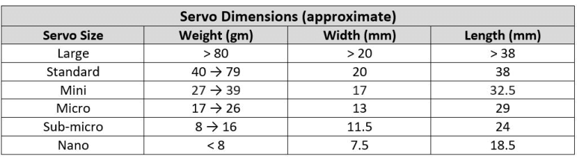
Sizes
The original standard size, for example (781-3058) designed for fairly large radio-control model aircraft with IC engines, now sits alongside more compact, less powerful versions. For really heavy applications even larger sizes are available.
Basic Interface
A modern microcontroller such as the Raspberry Pi RP2040 on the Pico board (212-2162) can drive several small servos without any extra hardware. The potentiometer shown in the demo circuit of Fig.3 sets the angular position of the servo arm – turn the knob and the servo will follow.
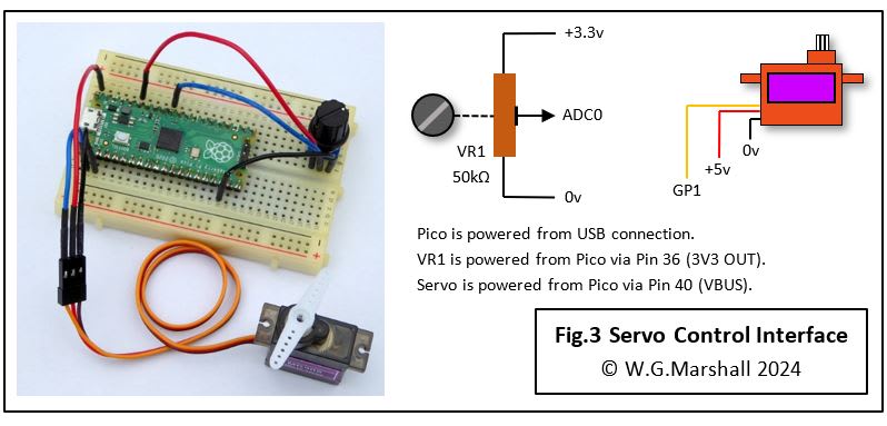
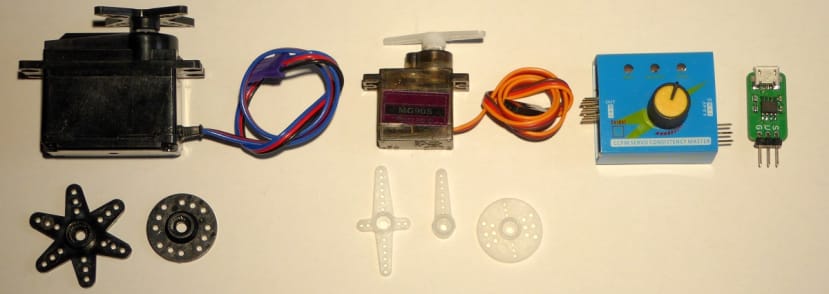
The metal-geared MG90S sub-micro servo shown here takes up to 250mA of current while moving and up to 700mA when stalled. A Pico VBUS power pin can just about cope with this load because its +5vdc output is derived directly from the USB connection. In principle, the chip can drive up to 16 of its GP outputs with independent PWM signals, but you will need a separate high-current supply for the motors! The pot is supplied from the +3.3Vdc output because that’s the limit for the Pico GP inputs. ADC channel 0 samples the analogue pot signal on GP26 and converts the result to a 12-bit number. The software performs a range conversion yielding a number between 0 and 180 which is then supplied to the Servo driver.

Design Considerations
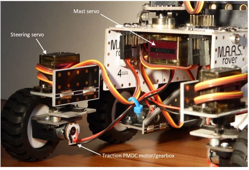
RC servos are ideal for prototyping small-scale machines or ‘toy’ robots. Although easy to work with, they are relatively fragile, even when equipped with metal instead of nylon gears. The high torque provided by the gearbox can move a heavy load, but maintaining position against a steady force will at best lead to vibration and noise, at worst motor burn-out as the large stall current takes its toll. RC servos are not ideal for moving the joints of a robot arm for example, because of the ever-present force of gravity. A better application is one in which the load largely disappears as soon as the target position has been reached: the use of servos for the M.A.R.S. robot steering (heading picture) is a good example.
A project with a lot of servos will need an appropriately large power supply to cater for the situation when all are running at the same time. Remember that each one contains electronics running off the same power rail as the motor. So, take care to provide each servo with its own wires or PCB tracks back to the power supply which should itself be separate from the MCU supply. A 100μF reservoir capacitor attached across each servo’s power connections can help stop surge currents causing glitched operation.
Articles in the series
This short series of articles is the basics of interfacing peripheral components to a microcontroller (MCU).
- Microcontroller Interfaces: LEDs and Lamps - In this first instalment, the simplest of display devices are considered: the single LED and the filament lamp.
- Microcontroller Interfaces: Switches and Buttons - In this second instalment, the simplest of input devices are considered: the mechanical switch and the pushbutton.
- Microcontroller Interfaces: Electromagnets and Solenoids - In this third instalment, I’ll show how special care is needed when designing an interface for an electromagnetic actuator.
- Microcontroller Interfaces: PMDC Motors - In this fourth instalment, we look at Permanent Magnet DC Motors, they are cheap, have linear characteristics and are very easy to control using the PWM units built-in to most modern microcontrollers. Interfaces can be as simple as a single transistor depending on the application.
- Microcontroller Interfaces: RC Servos (this article) - The RC Servo or Hobby Servo has been used to move the control surfaces of Radio-Control (RC) model aircraft for many years. It’s very popular with builders of both small humanoid robots and when converted for continuous rotation, wheeled robots.
If you're stuck for something to do, follow my posts on Twitter/X. I link to interesting articles on new electronics and related technologies, retweeting posts I spot about robots, space exploration and other issues. Click on Bill Marshall at the top of this article to see my back catalogue of DesignSpark articles.