Microcontroller Interfaces: Electromagnets and Solenoids
Follow article
 Dave from DesignSpark
How do you feel about this article? Help us to provide better content for you.
Dave from DesignSpark
Thank you! Your feedback has been received.
Dave from DesignSpark
There was a problem submitting your feedback, please try again later.
Dave from DesignSpark
What do you think of this article?
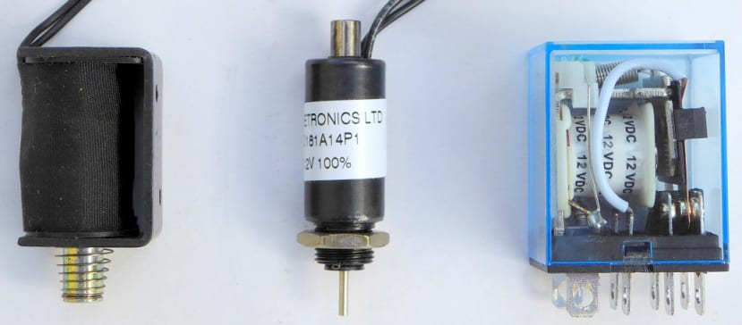
Left to right: Pull Solenoid, Push Solenoid, Miniature DPDT Relay.
Introduction
This is the third part of a short series of articles on the basics of interfacing peripheral components to a microcontroller (MCU) based system. Now for some devices that can damage your MCU if connected without a suitable interface; the ones that contain an inductive component, specifically a coil of tightly wound insulated copper wire. This category includes electromagnets, solenoids, relays and DC motors. The latter will be covered in a separate article, as will RC servomotors which don’t present an inductive load.
Aren’t magnetic devices like relays and solenoids obsolete; replaced by solid-state relays (SSR) and RC servos respectively? It’s true that they have their origins in the 19th century, but they still get used where a lot of linear force needs to be applied (electromagnets, solenoids), or where life-threatening voltages need to be visibly isolated, for example, 240Vac mains (relays). Polarized relays saw sterling service in railway signalling systems worldwide (still do in many areas), and telegraphic communications.
Some definitions
Electromagnet: A coil wound tightly around an iron/laminated core. When a current flows through the winding the core turns into a magnet with a North pole at one end and South at the other. Turn the current off, and the magnetism disappears. The magnetic ‘pull’ at each end is relatively small and only acts over a short distance, but it can be used to attract the end of a pivoted steel lever, perhaps triggering a complex mechanism.
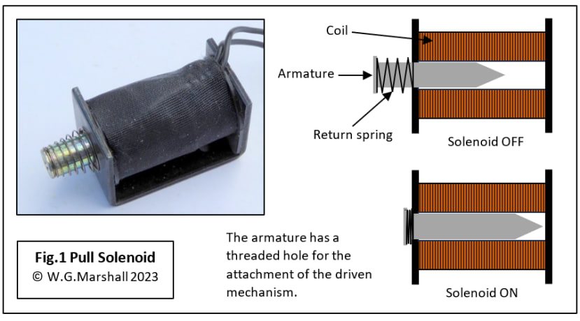
Solenoid: Very similar to the electromagnet except that the core is not fixed in the coil; it can slide in and out, and is known as an armature. When the coil is energized, the resulting magnetic flux pulls the armature in and centres it within the coil. It will be held there all the while the solenoid is ‘on’, and it will not move when the current is cut off without the action of an external force, such as that from a compressed return spring. There are two basic types: Pull (Fig.1) and Push (Fig.2).
Relay: An electrically operated switch. An electromagnet attracts a pivoted armature that has the moving contact (pole) of a switch attached to it. The small movement is enough to transfer the pole contact from one fixed contact to the other (Fig.3). The switch toggles back thanks to a return spring when the magnet is turned off.
I’ve also included a Polarized Relay (Fig.5) for completeness because it can have a third state: off, and requires the electromagnet to be energized to close either contact.
The ‘Pull’ Solenoid
Technically, all solenoids are of the pull variety. When a current flows through the coil, in either direction, the result is the same: a partially inserted armature core is pulled in and centred by the magnetic flux. One end of the core will be the North Pole, the other South just like the electromagnet.
The ‘Push’ Solenoid
Fit a push rod into the other end of the armature and you have a solenoid with a pull-push action (Fig.2). This particular device doesn’t have a return spring, so the ‘load’ will have to push the rod back in this case. Notice that these two solenoids use different mounting methods: the ‘Pull’ has a couple of M3-tapped screw holes in its outer frame, while the ‘Push’ fits through a hole in the target chassis and is secured with a single nut.

The Relay
The humble electromagnetic relay (Fig.3) is still used in large numbers for switching high-voltages and currents, providing the confidence of ‘air-gap’ isolation. The DPDT example shown here is only 3.5cm tall and yet it can control 240Vac mains voltage and a current of 10 amps.

When used just as an on/off switch and the normally-closed (NC) contact is ignored, the device is inherently ‘fail-safe’ because loss of coil power will allow the spring to open-circuit the load connection. On the other hand, when using both contacts in a changeover configuration, a drop-out may have serious consequences.
Microcontroller Interface for solenoid and relay
A typical circuit for driving these simple unipolar devices is given in Fig.4. This particular example was designed to drive a powerful electromagnet in an old punched paper tape reader restoration project of mine. The BD677 transistor isolates the delicate GPIO output of the MCU and acts as an electronic switch, turning the electromagnet on and off. It’s not a single NPN bipolar junction transistor (BJT) though, but two arranged in a Darlington configuration in one package. But first, let’s look at how this circuit is adapted to suit the push, pull and relay devices described above.
The primary design considerations are:
- Establish the power supply voltage. Don’t use the logic or analogue circuit supply rails – the relatively large switching currents can upset an MCU or sensor amplifier. The three devices in this article have voltage ratings marked on them instead of impedance and current. But you need to know the current in order to select a suitable transistor. I just use a multimeter to get a reading for resistance and then calculate the current from I = V/R.
- Select a transistor which can take the power supply voltage plus at least a 50% margin. Make sure its maximum current rating is at least double that required.
- Determine whether the current limiting resistor R1 is needed. This may be important if the Time Constant must be reduced by increasing the supply voltage (see later).

Pull solenoid interface
The solenoid is marked ‘+5Vdc’, and the multimeter indicates a resistance of about 55Ω, which gives a maximum steady ‘on’ current of 90mA. If we apply the rated voltage, then no R1 current-limiting resistor R1 is needed. Because the current is so low, there is no need for a 4A transistor either! Instead, my favourite for this type of situation is the TO92-packaged BC639: an 80V @1A NPN transistor.
Push solenoid interface
This is a +12Vdc solenoid but with the same resistance as the pull type. That gives us a maximum current of 220mA, still well within the range of a BC639. Again, no R1 is required.
Relay interface
The miniature relay is also marked as +12Vdc, but has a measured coil resistance of 155Ω and hence takes just 75mA of current. Once again, the BC639 can handle it, and R1 is not needed here either.
The Polarized Relay
This type of relay (Fig.5) provides a latched changeover action so that the switch position remains unchanged should the power supply fail. A good safety feature. The diagram should make it clear how this is achieved:
- A permanent magnet is used to hold the pivoted armature in one of two positions.
- The relay changes state when a current flows through the coils generating an electromagnetic flux, and setting up North and South poles at either end of the armature.
- If the permanent magnet North is then touching the armature North they will repel each other and the armature will rotate to the other side.
- Reversing the coil current causes the N-S poles of the pivoted electromagnet to swap over and the latter rotates back.
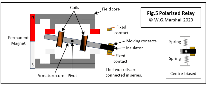
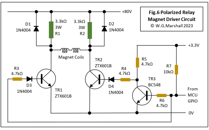
To enable this current reversal technique to be used, the driver circuit has two transistors arranged in a ‘bridge’ format (Fig.6). This particular circuit was designed to drive the polarized magnet in a 1960’s teleprinter interface project. Now, the teleprinter uses a centre-biased armature, where two springs hold the armature centrally between the contacts. In other words, they provide a third ‘centre-off’ position when the coils are not energized. The purpose of those springs was to improve the sensitivity of the magnet when it was driven directly from the ±80V telegraphic line. Obviously, that extra sensitivity to weak signals on a (perhaps miles) long communications line is not required now, thanks to the interface. I should also mention that the magnet device in the teleprinter does not have any electrical contacts. It’s not an electrical relay: like a solenoid, it’s the mechanical movement that matters. I’ll still keep referring to it as a relay because the lack of contacts does not affect the interface design.
Polarized relay interface
The bridge arrangement of Darlington transistors TR1 and TR2 (Fig.6), is controlled by TR3. When the GPIO output is high (logic 1), TR3 is fully on causing TR1 to be fully on and TR2 off. The current flows from right to left through the magnet coils. A logic 0 on the GPIO line reverses all the transistor states and coil current flows from left to right. An obvious question is: why not reduce the 80V supply and with it the values of resistors R1 and R2? To answer that question, I’ll need to bring in another characteristic feature of any coil: its inductance L.
Inductance is the tendency of a conductor to oppose a change in the current flowing through it. Even a straight bit of wire has some inductance, winding it into a coil massively increases it. In fact, it’s proportional to the number of turns squared. This means that when a voltage V is applied to a coil, the current rises exponentially to a value given by V/R where R is the coil resistance in ohms. So, R limits the final value of the current, but L determines how long it takes to get there. The coil is described as having a Time Constant τ = L/R which is the time in seconds it takes the current to rise to 63% of its final value. This is analogous to the time constant of a capacitive circuit where τ = CR, which is the time taken for the voltage across the capacitor to rise to 63% of its final value.
Does this time constant matter? For most relay and small-solenoid applications, a time constant of about 1ms is plenty quick enough. The two solenoids and a relay shown in Figs.1 to 3 are all about 1ms based on their internal coil resistance values. They are all voltage-rated components because no other resistance needs to be added. Things are different for the PTR and teleprinter magnets: they are current-rated with completely different characteristics.
Current-rated coils
Let’s go back to Fig.4. The PTR magnet coil has a resistance of a mere 0.5Ω, an inductance of 16mH, and a current rating of 1A. For this application, the steady-state force applied by the electromagnet is more important than its time constant. The electromagnetic force is proportional to the current I squared, so a large I would seem to be a good idea, That means there must be fewer turns of heavier gauge wire reducing both R and the inductance L. We will want to use a sensible voltage for the power supply, hence the use of a 10Ω current-limiting resistor with +12V. A snag is that the resistor has to dissipate about 10W of power in the form of heat when the solenoid is energized continuously. That’s why a relatively expensive 25W wire-wound part is specified. The resulting time constant is a perfectly respectable τ = 0.016/10.5 = 1.5ms.
Moving on to the teleprinter interface, we find an electromagnet with very different characteristics: the magnet coils have a combined resistance of 220Ω, an inductance of 4.5H, and a current rating of 22mA. Yes, that’s right: 4.5 whole Henries, not mH! It’s a legacy from the original telegraph line circuits. That gives us a time constant of 20ms which is way, way too slow. This magnet has to convert serial data pulses from the host computer to mechanical ‘signals’ driving the teleprinter mechanism. The serial data rate is 75bits/sec or 75baud, and the worst-case data, as far as switching is concerned is 101010101…. The bit interval is 1/75 = 13.3ms, which means that the magnet must be able to switch the armature, from one side to the other, in about a tenth of that time: 1.3ms. Clearly, a time constant of 20ms won’t work. That’s why the supply voltage is 80V with 3.3kΩ current-limiting resistors R1, R2. Using a high-voltage results in high resistor values to maintain the steady-state current of 22mA. Increasing the circuit resistance reduces the time constant, so now τ = 0.016/3520 = 1.3ms. Notice that I’ve ignored the saturation (on) voltages of all the transistors for the sake of simplicity: it won’t affect the result much.
In practice, you won’t be designing your own solenoids and relays. But, just like other components you need to know enough to select the right one for the job from a catalogue.
Relay control using Pulse Width Modulation (PWM)
PWM has long been used to control the temperature of electric heaters or the speed of DC electric motors, but relatively recently it has found another application: reducing the power consumption of relay coils. The driver circuit designs above for a unipolar relay or solenoid, have two states only, on and off. In order to operate the relay, a switching current must flow in the coil. Once the NO contacts have closed, however, a lower holding current can be used to keep them that way, and that’s where PWM control comes in. The input to the interface from the MCU is a PWM-modulated waveform at a high frequency (often 20kHz so you can’t hear it). The duty cycle of the pulses determines how long the current flows during each cycle. So, 100% means continuous, 50% means on for half the cycle, and 0% is off continuously. The relay coil can’t possibly switch at that frequency; instead it ‘sees’ an average coil current matching the duty cycle. It works like this:
- Use a 100% duty cycle for about ten times the time-constant interval to get the contacts switched over and settled down.
- Reduce the PWM to lower the coil current to just above the holding value. What this is depends on the particular relay, but a value for it is usually specified in the relay datasheet. If the device is operating in an environment involving shocks and vibration, then a higher current may be needed for reliable operation.
- To deactivate the relay, just reduce the PWM to 0%.
A useful white paper on Pulse Width Modulation (PWM) and Relays is available from TE.
Texas Instruments manufactures a PWM-based relay driver chip, the DRV120.
Next Time in Part 4
I’ll be looking at interfacing small brushed DC motors (PMDC).
Articles in the series
This short series of articles is the basics of interfacing peripheral components to a microcontroller (MCU).
- Microcontroller Interfaces: LEDs and Lamps - In this first instalment, the simplest of display devices are considered: the single LED and the filament lamp.
- Microcontroller Interfaces: Switches and Buttons - In this second instalment, the simplest of input devices are considered: the mechanical switch and the pushbutton.
- Microcontroller Interfaces: Electromagnets and Solenoids (this article) - In this third instalment, I’ll show how special care is needed when designing an interface for an electromagnetic actuator.
- Microcontroller Interfaces: PMDC Motors - In this fourth instalment, we look at Permanent Magnet DC Motors, they are cheap, have linear characteristics and are very easy to control using the PWM units built-in to most modern microcontrollers. Interfaces can be as simple as a single transistor depending on the application.
- Microcontroller Interfaces: RC Servos - The RC Servo or Hobby Servo has been used to move the control surfaces of Radio-Control (RC) model aircraft for many years. It’s very popular with builders of both small humanoid robots and when converted for continuous rotation, wheeled robots.
If you're stuck for something to do, follow my posts on Twitter. I link to interesting articles on new electronics and related technologies, retweeting posts I spot about robots, space exploration and other issues. To see my back catalogue of recent DesignSpark blog posts type “billsblog” into the Search box above.
Comments