Microcontroller Interfaces: LEDs and Lamps
Follow article
 Dave from DesignSpark
How do you feel about this article? Help us to provide better content for you.
Dave from DesignSpark
Thank you! Your feedback has been received.
Dave from DesignSpark
There was a problem submitting your feedback, please try again later.
Dave from DesignSpark
What do you think of this article?
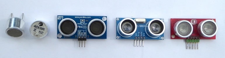
Sensor interfacing. From left to right: (a) Transmit and Receive ultrasonic transducers requiring a lot of interfacing hardware to make a rangefinder. (b) OTS PING))) rangefinder with on-board transmit/receive hardware and a 3-pin MCU connection. Host MCU handles time measurement and distance calculation. (c) OTS SRF-04 rangefinder with 4-pin connector. Still requires host MCU to handle all calculations. (d) OTS SRF-08 rangefinder with 5-pin connector. Communicates with host via I2C bus. Responds to range request with distance in cm or inches as required. Multiple addressable units can share the same two-wire bus.
Introduction
This is the first part of a short series of articles on the basics of interfacing peripheral components to a microcontroller (MCU) based system. I’ll go through some criteria that need to be considered when deciding which chip or board is best for your application – that choice will influence the design of peripheral interfaces. But first, let’s get some definitions out of the way to avoid confusion later:
The Central Processing Unit (CPU).
For the early computers, this was a whole boxful of valves, transistors or simple logic chips spread out on more than one board that performed the basic fetch and execution of maths and logical instructions. It did not contain any form of memory storage (apart from a few working registers and counters) and certainly no peripheral interfaces or I/O ports. Eventually, integrated circuit technology improved to the point where all the CPU functionality could be incorporated on a single ‘chip’:
The Microprocessor (MPU).
MPU devices even today, generally don’t possess any on-chip storage, with most of the pins providing access to the main internal address and data busses for the purpose of linking to high-capacity external memory, usually DDR SDRAM. The first 8-bit MPUs had 16-bit address busses yielding a maximum of 64KB of memory space, some of which was sacrificed to permit the inclusion of ‘memory-mapped I/O’. Until the recent introduction of the RP2040 MCU chip on the Pico board (212-2162) , all Raspberry Pi computer boards were based on microprocessor-type chips.
The Microcontroller (MCU).
Soon after the first 8-bit MPUs appeared, such as the Intel 8080, MOS Technology 6502 and Motorola 6800, it became obvious that they were never going to power serious ‘desktop’ computers (PC). Embedded control was a much better bet. That led to the development of the MCU, with on-chip program/data memory, and most important of all, latched 8-bit Input/Output Ports replacing the external data/address busses. A firm called Arizona Microchip introduced the first true MCU called PIC, short for Peripheral Interface Controller in 1976. Originally, engineers at General Instruments had designed it as a companion to a microprocessor, giving the latter I/O ports. Those engineers, realising its potential, left GI and formed the company we now call Microchip to make the game-changing PIC microcontrollers. PIC now stands for ‘Programmable Intelligent Computer’ apparently.
The Digital Signal Processor (DSP) and the Digital Signal Controller (DSC).
For the sake of completeness, I’ll just mention these two variations of the MPU and MCU respectively. Each contains special hardware and an extended instruction set to enable complex digital signal processing algorithms to be run in real-time. The Texas Instruments TMS320 family contains classic DSPs, while Microchip, who invented the term DSC, have their dsPIC ranges.
Which to choose?
When choosing a processor chip for an embedded application, you have a number of things to consider such as clock speed, measured in Millions-of-Operations-Per-Second (MIPS), program and memory capacity, and what sort of peripheral devices need to be attached. It’s that last item I’ll be looking at in this series of articles on peripheral interfacing.
So, how do peripheral devices influence the choice of processor chip? Crudely, it comes down to the number of pins it has dedicated to I/O. Designing at chip-level pretty much eliminates MPUs and DSPs for the reasons outlined above. That leaves MCUs and DSCs. Nearly all the pins on these chips are dedicated to General Purpose digital I/O (GPIO), usually, but not always grouped together as 8-bit Ports. These Ports form what used to be called ‘Parallel I/O’ as opposed to ‘Serial I/O’ such as UART, SPI and I2C. Most MCUs make all these serial port formats available too, plus in many cases, USB. The third type of I/O commonly available is Analogue, taking advantage of the on-chip ADCs and DACs. When it comes to your design, it’s just a question of matching the I/O requirements to a particular device from the family chosen to meet the speed/memory specification. Two recent projects of mine involved PIC24-based interfaces with very different I/O requirements: Creed 75 teleprinter and Elliott paper tape reader. Both are custom-board designs working at chip and discrete component level, and programmed in Assembler, ‘Bare-Metal’ code.
You don’t have to work at chip level though: there are literally thousands of board-level products on the market ranging from thumbnail-sized ‘tiny’ modules, through ‘mini’ modules such as the Raspberry Pi Pico, to ‘development’ boards such as MikroElektronika’s Clicker 2 (170-8233) , the legendary Arduino series, Microchip’s Curiosity range, and of course, the Raspberry Pi 4.
Development
Basic peripherals such as single-LEDs and pushbuttons are easily attached to any single GPIO pin with a minimum of extra components; perhaps just a single resistor. Analogue signals can obviously be connected to on-chip ADCs and DACs via pins designated as analogue I/O. Increasingly though, complex peripheral circuit functions such as accelerometers, gyroscopes and wireless comms, are being made available in chip form, communicating with a host processor via a serial bus. This has led to an explosion in the variety of peripheral modules available that just plug-in to development boards fitted with matching sockets. The ‘Click’ range from MikroElektronika is extensive and growing rapidly. Their MikroBUS standard sockets are not confined to their own processor boards; Microchip Curiosity (187-6209) boards feature them and adapters for the Arduino Shield format (823-1883) and Raspberry Pi Hat standard (162-3385) connectors are available. These modular systems may make development easy, but production board design will still need the engineer to understand how to interface these peripheral devices at component level. Admittedly, the effort involved in embedded application development is shifting from hardware design to software coding.
Basic digital output – a single LED
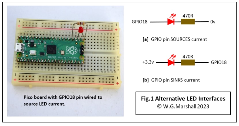
Let’s start with the simplest of display devices: the single LED (Fig.1). The host MCU is an RP2040 – the key component of a Raspberry Pi Pico module. The function is just digital, LED on or LED off, so a single GPIO pin set to be an output does the job and the only other component is a current-limiting resistor. There two ways to wire this up: (Fig.1a) with the LED anode to the GPIO pin and the cathode to 0V via the resistor, or (Fig.1b) with the anode to +3.3v and the cathode to GPIO via the resistor. Either will work, but the logic is reversed, so for circuit (a) GPIO = 1 will turn the LED on, but for (b) GPIO = 0 is required. Both designs work because the GPIO port driver is symmetrical and can either supply (SOURCE) current (a), or SINK it (b). Some older MCUs can only sink current.
Calculating the resistor value
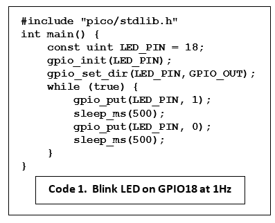
This is not very critical. A small LED like this only needs a few milliamps of current to light up and the Pico GPIO current defaults to 4mA. To calculate the resistor value using Ohm’s Law R = V/I, we know I = 4mA and V = the voltage across it. V = 3.3 minus the LED forward voltage VF taken from a datasheet. LEDs have different values for VF depending on their colour. Red VF = 1.7v. For reference, Yellow = 2.1v, Green = 2.2v, Blue and White = 3.5v. For the Red LED this gives a resistor voltage of 1.6v and thus a resistor value of 400Ω. A standard value of 470Ω will do just fine. Note that the Pico current setting does not represent a current-limiter operation which would have removed the need for a resistor: leave it out and the GPIO output driver will be overloaded and probably burn out. Check out the C code that flashes the LED once per second (Code 1). Notice that it uses a useful power-saving feature as a timer: sleep_ms(500) powers down the processor core for 500ms.
Basic digital output – a filament lamp
A filament lamp interface is more complicated (Fig.2) because the lamp requires a lot more current than the GPIO pin can supply; 10 times as much in fact. Although it doesn’t need a current-limiting resistor, it does require 6v across it to light up. Hence the ‘Power-Darlington’ BJT transistor.
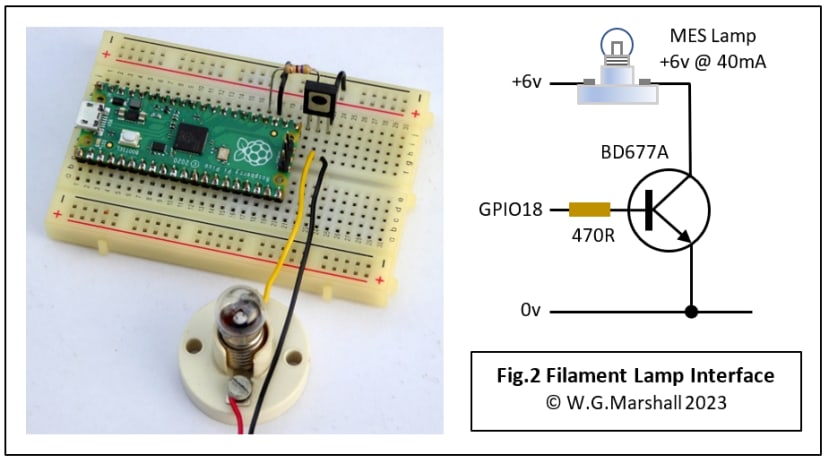
Darlington transistors have a huge gain, so a tiny Base current will turn it full-on like a switch. They are fast too, so are frequently used as buffers between GPIO lines and high-voltage or high-current peripheral devices. The BD677A can handle a 4A current and will have no problem with this weedy torch bulb. A 12v 21W car direction indicator bulb should be within its capabilities, but the switch-on surge of any filament lamp of this size might just be too much for it.
Next Time in Part 2
I’ll be looking at simple mechanisms for GPIO input: pushbuttons and switches. The mechanical nature of these devices means that the interfaces require special attention to ensure reliable operation.
Articles in the series
This short series of articles is the basics of interfacing peripheral components to a microcontroller (MCU).
- Microcontroller Interfaces: LEDs and Lamps (this article) - In this first instalment, the simplest of display devices are considered: the single LED and the filament lamp.
- Microcontroller Interfaces: Switches and Buttons - In this second instalment, the simplest of input devices are considered: the mechanical switch and the pushbutton.
- Microcontroller Interfaces: Electromagnets and Solenoids - In this third instalment, I’ll show how special care is needed when designing an interface for an electromagnetic actuator.
- Microcontroller Interfaces: PMDC Motors - In this fourth instalment, we look at Permanent Magnet DC Motors, they are cheap, have linear characteristics and are very easy to control using the PWM units built-in to most modern microcontrollers. Interfaces can be as simple as a single transistor depending on the application.
- Microcontroller Interfaces: RC Servos - The RC Servo or Hobby Servo has been used to move the control surfaces of Radio-Control (RC) model aircraft for many years. It’s very popular with builders of both small humanoid robots and when converted for continuous rotation, wheeled robots.
If you're stuck for something to do, follow my posts on Twitter. I link to interesting articles on new electronics and related technologies, retweeting posts I spot about robots, space exploration, and other issues. To see my back catalogue of recent DesignSpark blog posts type “billsblog” into the Search box above.
Comments