Integrating IO-Link Sensors and Actuators with PLCnext Part 1: Introduction
Follow article
 Dave from DesignSpark
How do you feel about this article? Help us to provide better content for you.
Dave from DesignSpark
Thank you! Your feedback has been received.
Dave from DesignSpark
There was a problem submitting your feedback, please try again later.
Dave from DesignSpark
What do you think of this article?
Upgrading the PLCnext controlled can crusher with IO-Link connectivity and devices.
Introduction
In this series of articles we’ll be upgrading our existing PLCnext controlled can crusher with IO-Link connectivity, to enable the installation of smart sensors and actuators for improved monitoring and control.
We’ll explore what IO-Link is and the hardware provided by Phoenix Contact to add support to the PLCnext ecosystem, as well as selecting two devices to integrate with the can crusher. Initial setup will also be done to configure the controller, in readiness for mechanical installation, cabling and final configuration.
What is IO-Link?
IO-Link is a low-cost, bidirectional industrial sensor and actuator communication standard that helps simplify connections between another Fieldbus, such as industrial Ethernet, and the end device — typically sensors and actuators. Running over common 3-wire cables often used with simpler sensors and actuators, IO-Link offers far greater functionality for little extra cost; extended sensor diagnostics, parameter setting and control are all offered, amongst other features
Widely regarded as enabling concepts that are central to Industry 4.0, IO-Link can bring back diagnostics data to a central location far quicker than sending an operator to check upon a sensor — essentially bringing communications capability to the “last metre”, which would typically only carry an analogue or digital signal.
Backwards compatibility is also part of the standard, meaning that traditional binary sensors and outputs can still be used within an IO-Link system. The same also applies to binary IO-Link sensors, which can be integrated into systems that use traditional digital inputs; parameterisation of a binary sensor is still possible and allows for settings to be cloned across sensors, opening the door for productivity increases.
IO-Link Architecture
IO-Link is designed as a point-to-point interface using either wired or wireless connections. A master typically has one or more ports to connect to devices or can act as a “hub” to allow the connection of up to sixteen traditional switching sensors and actuators.
A number of standard baud rates are used for serial communication, including 4800, 38400 and 230400 baud. The slowest baud rate results in a cycle time of approximately 2.3 milliseconds, which is fast enough for most applications.
IO Device Description
Given that IO-Link enables device parameterisation, a standard file format was created that describes the capabilities. Typically, there is one main file and several optional files, including language translations (for parameter names and textual data) as well as graphics in PNG format.
The IODD files use XML formatting with a structure that is compliant with ISO 15745 “Industrial automation systems and integration – Open systems application integration framework”, where the main file contains a profile with “DeviceIdentity” and “DeviceFunction” objects, as well as a communication network profile that sets up the IO-Link protocol.
Variants are supported within an IODD, allowing manufacturers to produce one file that describes a number of devices. An example use case of this would be a device that has the same set of parameters but different part numbers due to differing mechanical packages.
Adding IO-Link to the PLCnext
Phoenix Contact have produced a number of options for adding IO-Link capabilities to the PLCnext ecosystem, each of which have their own particular benefits.
Profinet IO-Link Master
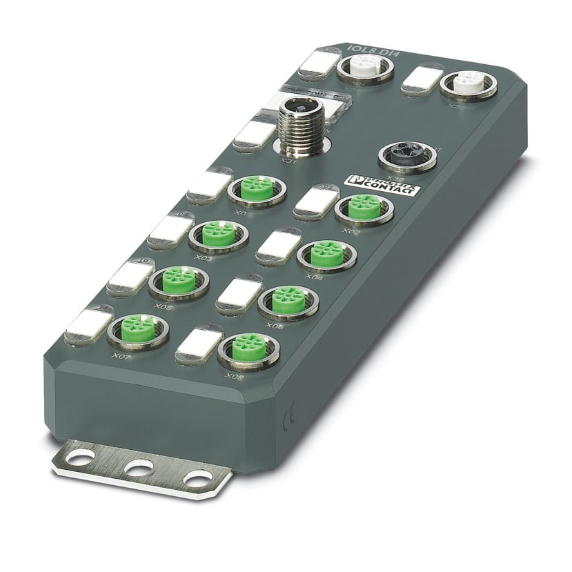
The AXL E PN IOL8 (241-6033) module is an Axioline E compatible IO-Link master module utilising Profinet for communication with the PLCnext ecosystem. Input/output capabilities of this module include four IO-Link ports that can be reconfigured to support eight digital inputs or outputs, acting as a hub for traditional devices.
Mechanically, the module is compact at approximately 200mm long and designed for wall mounting, with a plethora of M12 connectors for network, power and external device connection. Utilising Profinet means that the master module can be mounted remotely from a PLCnext controller (up to the length limit of an Ethernet connection), close to where the sensors and actuators are installed avoiding the twenty-metre IO-Link cable length limit.
Axioline F IO-Link Master
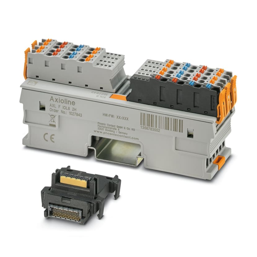
For closer integration with a PLCnext system, the AXL F IOL8 2H (217-6285) module is compatible with the Axioline F bus utilised by PLCnext controllers and comes supplied with a bus base connector ready for snapping onto DIN rail.
This IO-Link master features eight ports, each capable of providing a digital input or output at up to 200mA per channel when configured for DI/DO modes. This solution is ideal for when a controller is located closer to the end devices, within the twenty-metre length limit.
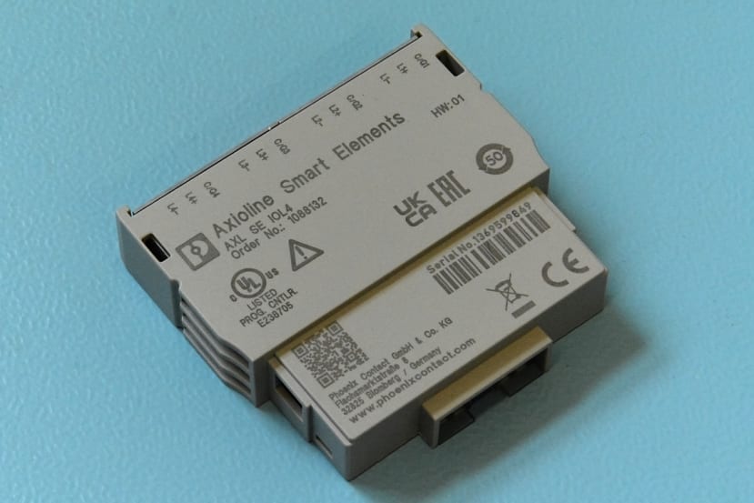
Axioline Smart Elements IO-Link Master
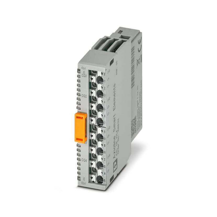
The solution we eventually settled on utilises the AXL SE IOL4 (220-5659) Smart Elements module. As we have an existing Smart Elements carrier with a spare slot, plus limited space on the DIN rail, this proved to be the best fit.
Again, four IO-Link channels are available that can be operated in digital input or output mode, with up to 200mA per channel sourced. Module integration is easily done through PLCnext Engineer, along with parameterisation through IODD files imported into the tool.
The module is also supported by the “IOL-CONF” parameterisation tool that supports online commissioning, or from prepared record files. This tool also supports other Axioline F IO-Link masters.
Device Selection
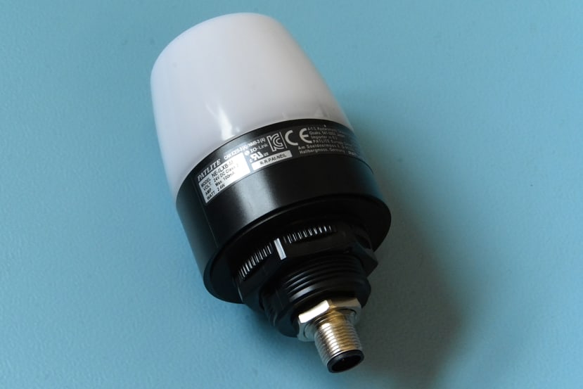
As we wanted to be able to display more operational states than can currently be shown with two simple indicators, we selected the NE-ILXB-M LED beacon (193-6829) from Patlite.
Features of the NE-ILXB-M include a seven colour controllable LED with continuous and flashing patterns, a buzzer with eight different sounds, a touch sensor, plus a digital NPN input and 4-20mA current loop analogue input. All of the available process data is accessed via IO-Link, plus parameterisation is supported allowing for configuration of the touch sensor and input behaviours.
Various operating modes are offered including “colour specification” where a colour and buzzer pattern is commanded over IO-Link, “level”, “analogue input” and “digital input”. The last three modes can be parameterised then run as a standalone device — for example, in analogue mode the input can map to a range of colours and turn the buzzer on when a high level is reached.
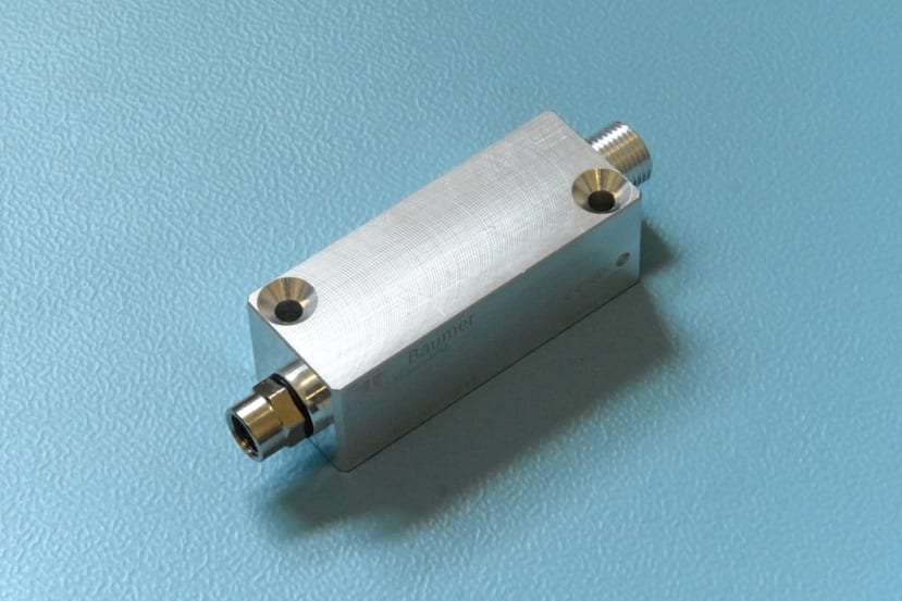
To measure the force applied when a can is crushed, a suitable load cell (204-2764) with a measuring range of 500 kg was selected. This measures compressive forces which, in our case, drastically simplifies mounting of the sensing element.
As the load cell uses a strain gauge that has an analogue output designed to be connected to a Wheatstone bridge, we purchased the DAB10-AL IO-Link bridge amplifier from Baumer. This features a 24-bit ADC for accurate measurements, paired with a 14-bit DAC to drive the bridge.
Parameterisation options supported by the amplifier include unit selection with the option of newtons, kilograms and more; teach-in offset and taring, correlation to a known force and selecting the function IO mode. Additional supported functions include low pass filtering, peak value memory, sample and hold mode and two digital switching points.
With all our components chosen, two IO-Link ports remain available on the Smart Elements module, providing room for further expansion.
Preliminary Setup
Before installing any hardware we set up the PLCnext Engineer project with the new IO-Link master module and IODD files describing our devices.
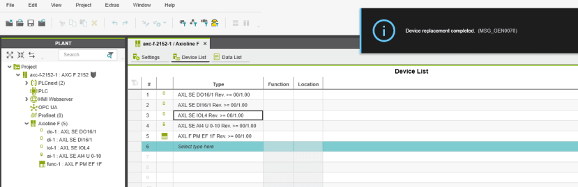
The first step is to configure the Axioline F bus to make it aware of the master module. Slot four happens to be currently occupied by the AXL SE SC-A blanking cover, which was replaced by clicking on the type dropdown and selecting the AXL SE IOL4. A notification was generated confirming the device replacement.
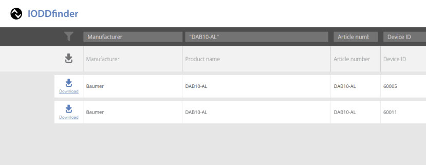
We then downloaded the IODD files for both devices from the IODDFinder website. This useful resource is provided by the IO-Link Consortium and acts as a database for manufacturer IODD files, accessible in a number of ways.
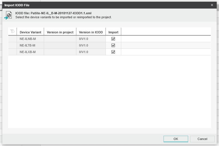
Importing IODD files is as easy as heading to “File”, “Import” then “Import IODD file(s)” and selecting the appropriate XML file. If there are multiple variants within an IODD, a window appears that allows for all or a subset to be imported.
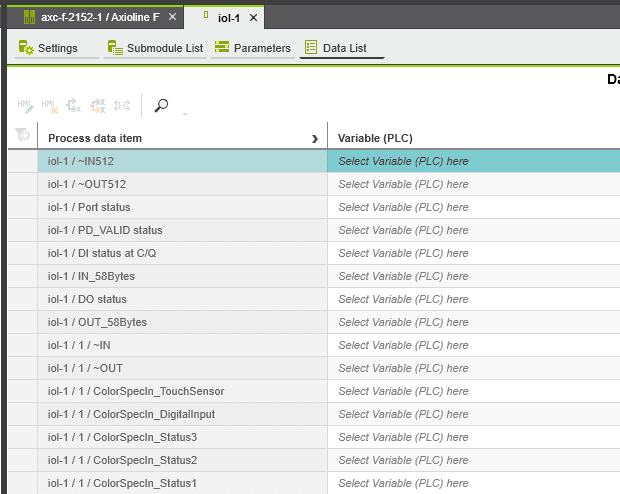
Double-clicking on the “AXL SE IOL4” item in the “Plant” menu then opens a tab where device types can be assigned to the port. We assigned both the beacon and measuring amplifier to ports one and two respectively. Process data items are then populated in the “Data list” screen, based upon the parameters present in the IODD file.
For now, we’ve completed the initial setup of the IO-Link devices. A deeper dive into parameterisation and usage will be done when we integrate the devices with the PLC program.
The Upgrade Plan
As it currently stands, the can crusher lacks instrumentation for crush force and utilises traditional indicators for operational status.
To support fitting the new Patlite beacon, as well as removing the normal indicators, a new aluminium top plate was designed and manufactured by a laser-cutting service.
The crusher sub-assembly requires modification to be able to accommodate the extra height introduced by the load cell. Given the most suitable place to fasten the sensor is between the cylinder rod end and crush plate, longer tie bars will be fabricated to provide suitable Z-height.
Other changes are primarily electrical and software, including installing the IO-Link master module, adding supporting cabling for both devices and updating the PLC program to use the new beacon for status indication. The web-based dashboard will be extended to add a graph of the force exerted on the can.
Conclusion
In this article, we’ve explored what IO-Link is and explored the features it presents, as well as looking at hardware produced by Phoenix Contact for adding connectivity to the PLCnext ecosystem.
We settled on the Axioline Smart Elements IO-Link master, selected a suitable set of devices and took a look at how easy it is to get started with smart devices inside PLCnext Engineer.
In part two of this series we’ll be performing the mechanical modifications to the can crusher, installing the new hardware and modifying the PLC program logic to make use of the new sensors and actuators.
Comments