How do I use the Flythrough camera mode in DesignSpark Mechanical?
Follow tutorial
 Dave from DesignSpark
How do you feel about this tutorial? Help us to provide better content for you.
Dave from DesignSpark
Thank you! Your feedback has been received.
Dave from DesignSpark
There was a problem submitting your feedback, please try again later.
Dave from DesignSpark
What do you think of this tutorial?
This tutorial requires:
DesignSpark Mechanical V6.0Flythrough is a display mode intended to give you the impression you are inside the model looking around.

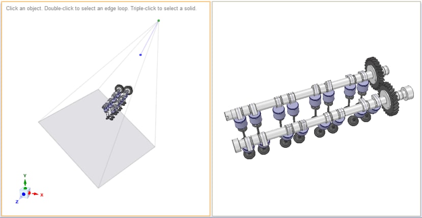
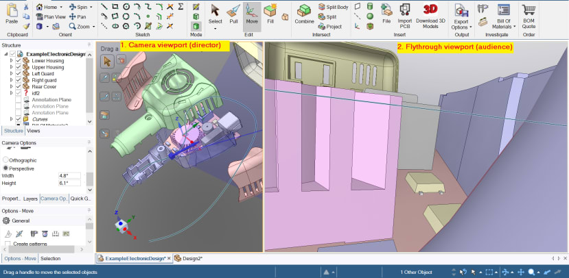
When setting up a flythrough mode, typically the screen is split with one viewport to show the camera position and one for flying through.
A short video tutorial and the key components of setting up a flythrough are shown below:
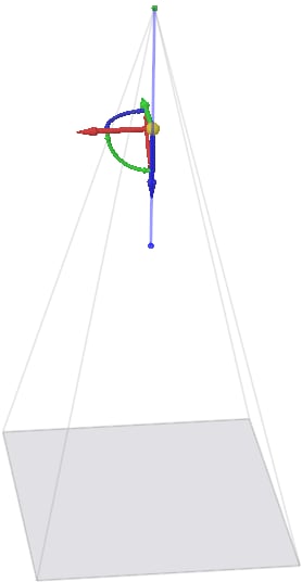
1. The camera
The green dot at the top of this ‘pyramid’ is the camera lens/eye. The blue line is the line of sight when looking straight ahead. The ‘pyramid’ itself is your sight cone or field of vision at any given position of the ‘eye’.
2. Viewports
These can be created using ‘camera options’ or the ‘split window’ drop-down in the display tab. Viewports can also be useful in examining your model from multiple perspectives at the same time. Edits in one will be reflected in the others too.
For flythrough animation, one viewport is needed for your camera - positioning and giving it directions to move along.
The second viewport is from the camera lens perspective and is what you’d record.
3. Setting a trajectory for the camera to navigate
By default, flythrough will simply switch from orthographic to perspective mode and give you a quick zoom in & out of your model.
To really explore the internal features of your design, you will need to give the camera a path to follow. This can be using any of our 2D sketch tools like spline, circle, etc.
In the video tutorial below, we use a spline curve set at our preferred location as the guide for the camera to follow.
Additional reading
More details about the Flythrough mode are explained in the software help documentation. This is accessible within DesignSpark Mechanical, usually via the ‘F1’ key shortcut. Search for ‘Flythrough’ in the help document.