Hands-on with PowerLogic PM8000 Part 2: Configuration and Use
Follow article
 Dave from DesignSpark
How do you feel about this article? Help us to provide better content for you.
Dave from DesignSpark
Thank you! Your feedback has been received.
Dave from DesignSpark
There was a problem submitting your feedback, please try again later.
Dave from DesignSpark
What do you think of this article?
Schneider Electric PowerLogic PM8000 basic configuration and usage.
In Part 1 of this series, we took a look at the components used and the assembly of a test setup for getting hands-on with the Schneider Electric PowerLogic PM8000 (913-9766) . For a general introduction to the meter and its standout features, see the earlier article, A First Look at Schneider Electric PowerLogic PM8000 High Performance Meters.
Final cabling

We had previously wired the PM8000 main unit, cabling voltage pick-off and CTs for the three phases plus neutral, along with earthing and, of course, meter interfacing.
A suitable 5-core cable and an industrial power plug and socket were then used to connect up a 3-phase supply and load.
- IP44 Red Cable Mount 3P + N + E Industrial Power Plug (821-1955)
- IP44 Red Cable Mount 3P + N + E Industrial Power Socket (821-1930)
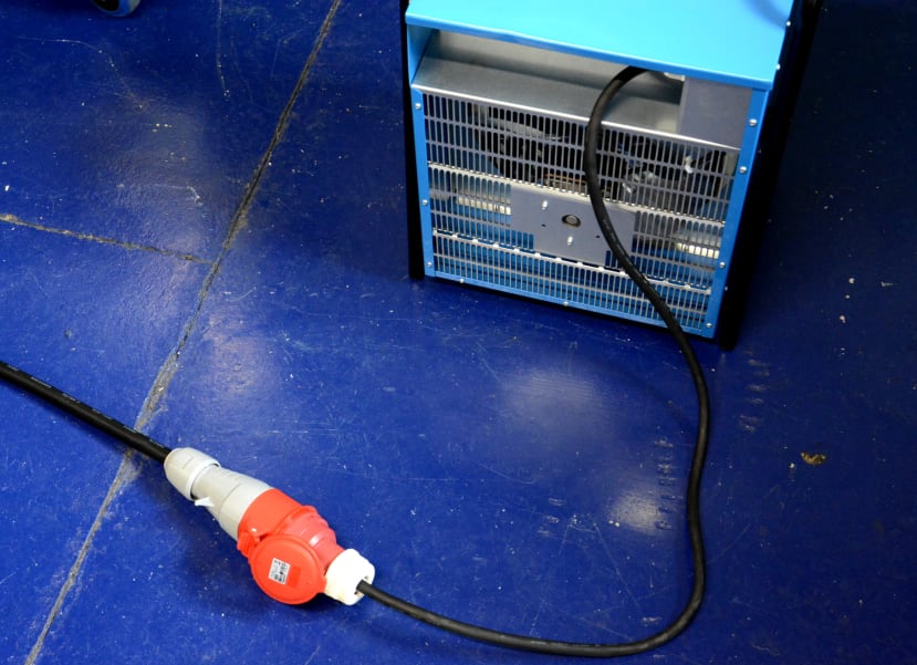
Connected to the load side of the meter we have a 15kW industrial fan heater.
Control voltage was supplied via a separate circuit cabled with a length of blue “arctic” cable.

The front panel was connected up to the meter unit using the supplied RJ45 cable.
Current measurement

Extract from page 58 of the User Manual.
The meter is capable of directly measuring currents up to 5A. The User Manual provides current transformer (CT) wiring details for 3 and 4-wire systems, with each using 3x CTs.
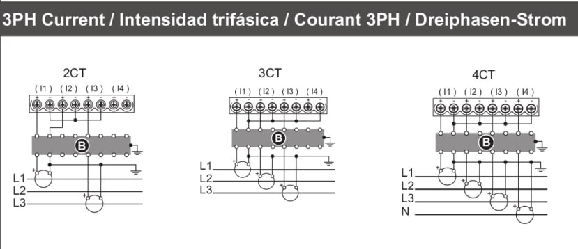
However, the meter has a total of four pairs of current measurement terminals and page 3 of the Installation Instructions PDF shows the I4 pair being used with a CT on neutral, as we have.
Setup
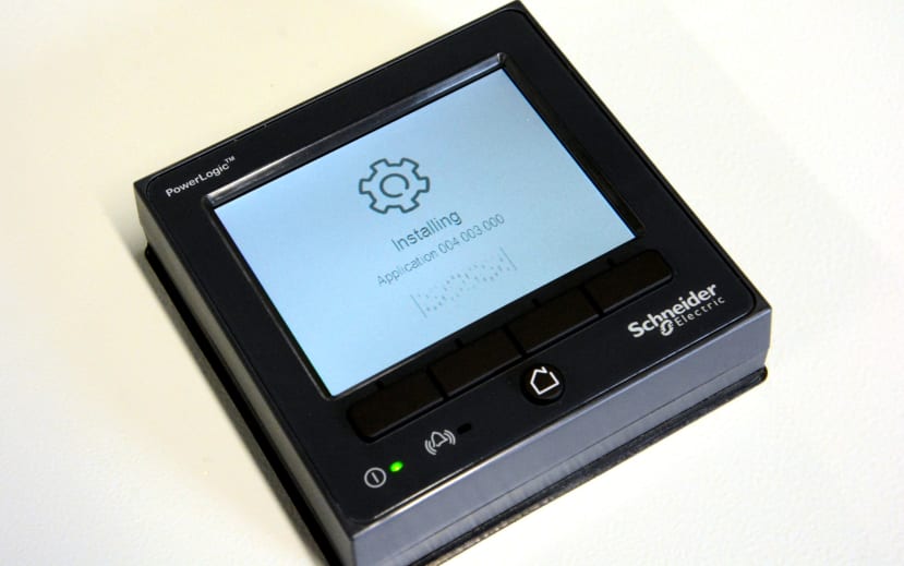
On the first power-up, the meter appears to download and install an update.
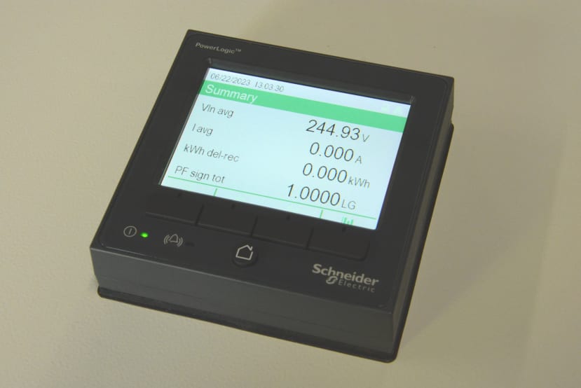
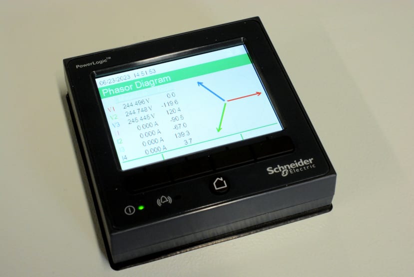
Then after a brief delay the meter home screen is displayed, which provides us with voltage, current, kWh and power factor readings.
There are three options available to us for meter configuration:
- ION Setup (Windows tool)
- Web interface
- Display panel
We decided to proceed using the web interface.
Logging on

The PM8000 is supplied configured with a static “link local” IP and so when we first connect we will need to use the URL:
https://169.254.0.10
Following which, we will receive a security warning since the meter is using a self-signed SSL certificate. Hence we need to select to accept the risk and continue. What this means is that we cannot verify the authenticity of the endpoint, but communications with it should be secure. This is less of an issue when you know that you are connecting to a local device and in any sort of significant deployment it’s likely that real SSL certificates — e.g. issued by IT security or support — would be used, which can easily be uploaded to the meter via its web interface.
We can log on using the default username and password of “USER1” and “0”.

Once logged in we are then presented with a set of basic readings.
Ethernet
Before getting on to exploring the various measurements available, we will first configure the device to use DHCP, via the Setup → Ethernet page. Note that we could just as easily configure some other static IP.
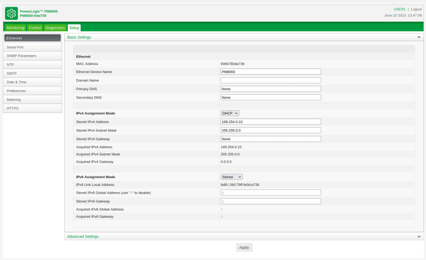
Once applied we can then re-connect via the new IP addresses and will have to once again accept the warning before we can log back in.
Note that there are all sorts of more advanced settings which may be configured via this page, such as enabling DNP and ION over TCP, and enabling Modbus TCP, SNMP and SSH access. We can also disable the web server or configure a non-standard port number should we wish.
While we won’t get into details in this article, the serial port may similarly be configured for use with ION, DNP and Modbus RTU. In addition to which it may be used for GPS time sync.
Time synchronisation
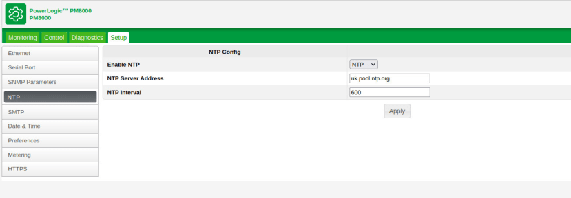
One other setting that we made before moving on to metering setup was to configure NTP, so that the time can be synchronised with reasonable accuracy via the Internet (or more typically this might be a LAN NTP server). Once applied the meter synchronised itself to UTC time.
Again the PM8000 is incredibly flexible and there are a number of other time sync options which we won’t get into details of here, such as using GPS or IEEE 15888 PTP for much higher accuracy synchronisation, which may prove highly beneficial if using meters with EcoStruxure Power Monitoring Expert, or perhaps to enable capturing precisely timestamped COMTRADE files.
Metering
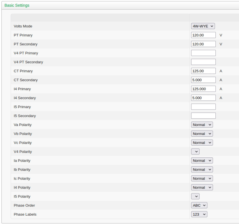
Now that we can access the PM8000 via a convenient IP address the next priority is to configure the metering settings via Setup → Metering. Here we can configure key parameters such as the Volts Mode, PT and CT details if used, voltage and current polarities, and phase order.
In our case, we have:
- A 4-wire wye configuration 3-phase supply
- 230V nominal voltage (L-N)
- 50Hz nominal frequency
- 125:5 ratio CTs on the 3x live phases
- 125:5 ratio CT on neutral (I4)

Above we can see the parameters set via the Basic Settings and Advanced Settings pages. Note that although the UK nominal single phase mains voltage is, like much of the world, 230V, this is with a tolerance of +10%/-6% and in practice, you tend to see around 240V — which was the standard pre-harmonisation and what a lot of transformers in the UK would still be set to use.
Basic usage
Now we get on to basic usage and here we will just cover a small subset of the available features. Note that we’ll be using the web interface, but the same information is also available via the panel.
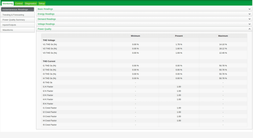
Earlier we saw the Basic Readings panel of the Instantaneous Readings tab, which also has panels which may be expanded for Energy Readings, Demand Readings, Voltage Readings and Power Quality. Above we can see the instantaneous readings for power quality, which are expressed as voltage and current THD, with the latter providing THD 3s, K factor and crest factor measurements.

The Trending and Forecasting panel meanwhile allows us to plot maximum, minimum and average values for a variety of targets, along with max, min and avg forecasts for these also. This panel not being particularly interesting at this point, since there was no load online.
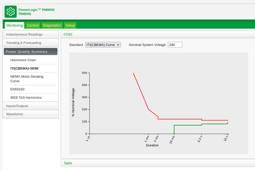
The Power Quality Summary menu provides Harmonics Chart, ITI (CBEMA) and SEMI standards, NEMA Motor Derating Curve, EN50160, and IEEE 519 Harmonics options.

EN50160 is the standard which specifies the power quality characteristics which must be met at the user supply. Here we can get details of things such as power frequency, supply voltage, harmonic voltage, and supply voltage swells, dips and interruptions, with figures for limits exceeded and compliance.
Final words
The PowerLogic PM8000 is absolutely packed with features and we’ve barely scratched the surface of what it is capable of. For example, we’ve not covered the configuration of alarms and alerts — the latter can even be sent via e-mail — power quality configuration, data logging, or waveform recording for power quality events. Much of this more advanced functionality must be configured via ION Setup and this is something which we may cover in future articles.