Hands-on with PowerLogic PM8000 Part 1: Test Setup
Follow article
 Dave from DesignSpark
How do you feel about this article? Help us to provide better content for you.
Dave from DesignSpark
Thank you! Your feedback has been received.
Dave from DesignSpark
There was a problem submitting your feedback, please try again later.
Dave from DesignSpark
What do you think of this article?
Building a 3-phase power metering test setup with a Schneider Electric PM8000.
In a previous article, we took a first look at the Schneider Electric PowerLogic PM8000 family of high-performance energy meters, which boast a wealth of features, notably including power quality (PQ) analysis and compliance monitoring to IEC standards, support for IEEE 1588 Precision Time Protocol (PTP) for high accuracy time synchronisation, and root cause analysis via the EcoStruxure Power Monitoring Expert (PME) software.
In this two-part series of articles we will first cover the construction of a test setup for a PM8000, followed in the second part by configuration and basic use of the energy meter.
WARNING: Please note that this is not an installation or how-to guide and rather instead simply a build log for a bench test setup. Please consult the vendor documentation and the wiring regulations for your country etc. for appropriate installation guidance.
Components
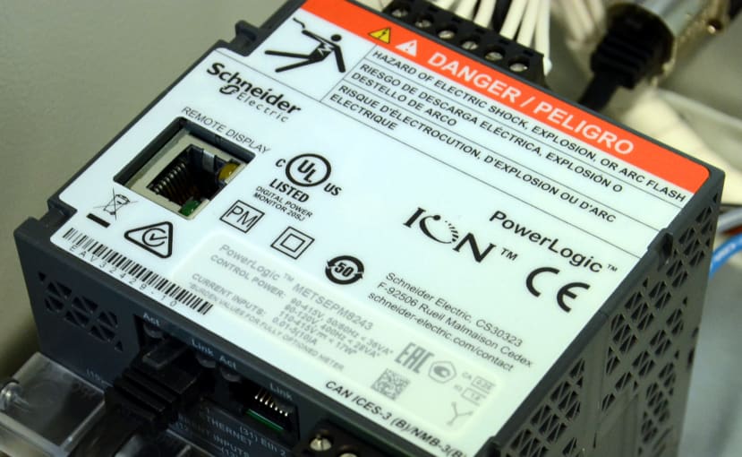
The meter model that we’ve selected is the Schneider Electric (SE) METSEPM8244, which features a DIN rail-mounted main unit and a display which may be remote-mounted for maximum flexibility. Since the meter current measurement terminals are only rated up to 5A, Schneider Electric METSECT Series current transformers (CTs) with a rated current of 125A will be used with this.
The components used are as follows:
- Schneider Electric 3 Phase LCD Energy Meter (913-9766)
- Schneider Electric METSECT Series Toroidal Ring Current Transformer, 125:5 (913-9734)
- Schneider Electric Spacial CRN Series Steel Wall Box (707-9154)
- Schneider Electric Metal Mounting Plate (375-8459)
- Phoenix Contact Perforated DIN Rail (248-2162)
- Phoenix Contact Grey UT 35 Feed Through Terminal Block (624-6921)
- Phoenix Contact AGK 4-UT 35 Series Pick-Off Terminal Block (804-3345)
- Phoenix Contact, ZB 16:UNPRINTED Zack Strip (856-8778)
- Phoenix Contact UISLKG 35 – Installation Ground Terminal Block (648-3625)
- Phoenix Contact PT 2.5/S-QUATTRO-PE Earth Terminal Block (123-7997)
- Phoenix Contact End Stop (803-9481)
- Lapp SKINTOP Series Metallic Nickel Plated Brass Cable Gland, M20 (405-8839)
- Neutrik etherCON CAT6A D shape Connector (121-6998)
- Binder 720 Female 5-contacts (046-9014)
- Binder 720 Female Dust Cap (734-5763)
- Binder 720 Male 12-contacts (046-9070)
- Binder 720 Male Dust Cap (734-5751)
- HellermannTyton Spiral Wrap, I.D 4mm, 20mm (030-5481)
- HellermannTyton WIC1 Snap On Cable Marker Kit (133-1752)
- HellermannTyton NGM Series Grey Nylon Cable Gland, M32 Thread (863-7928)
A suitably sized steel wall box and mounting plate will be used to house the components, bearing in mind that 25mm2 3-phase cabling will need sufficient space for conductors to be separated out, routed through the CTs and then terminated via DIN rail terminals.
The meter will be interfaced via Ethernet, however, RS-485 will also be brought out in case this is required for future use. Likewise, there are no immediate plans to make use of the digital inputs and outputs, but these will also be brought out to enable future use. Serial and I/O connectors will make use of Binder 720 series connectors, while Ethernet will be fed-through using a Neutrik etherCON.
Assembly

Where possible we prefer to fabricate holes in enclosures using sheet metal punches instead of using a step drill or hole saw, as these provide a much nicer finish and make less mess. Although a pilot hole does need to be drilled first so that the punch can be fitted in place.

We decided to have the enclosure with the gland plate at the top, as this is where the connectors would be located, which meant swapping the door hinges across if we still wanted it to swing out to the left. This was a quick job which just required removing the two pins securing the door, then unbolting the hinges and swapping them across to the other side.
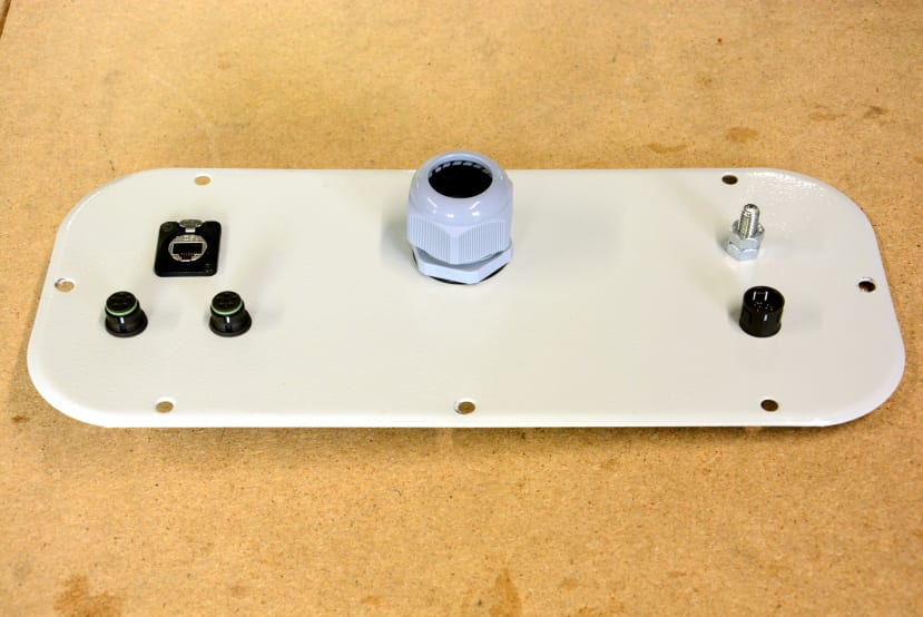
Above can be seen the gland plate, with a 32mm gland for 3-phase cabling, plus Ethernet, and Binder 720 connectors for RS-485 and I/O.

On the bottom of the enclosure, we have another 32mm gland, plus a 20mm gland for control power cabling.

The nice thing about the PM8000 models with a remote display is that this can be mounted in an enclosure door with only a single round hole.

The back side of the door can be seen above, with the plastic clamp plate and lock nut for the PM8000 display.
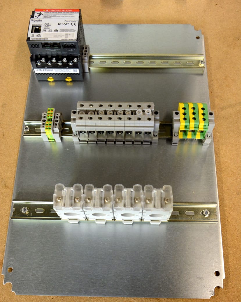
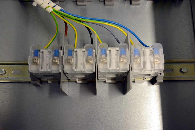
The assembled mounting plate, complete with DIN rail, PM8000 meter and terminals can be seen above. The grey terminals are for 3-phase power and there are 8 in total, with bridged pairs for L1, L2, L3 and N. This allows the supply to be passed through, with connection also to the voltage terminals on the PM8000.
A cautionary tale
Even with a single vendor’s products there can seemingly be numerous suitable options for things such as DIN rail terminals with a given termination type, voltage and current rating — and what follows is a cautionary tale!
In selecting DIN terminal blocks for the 3-phase power connections there were two Phoenix Contact ranges which seemed to fit the bill: UK 35 N and UT 35. One of the key differences between the two being that the latter are ATEX certified.
Initially, UK 35 N type were selected and bridges used to create pairs, such that power could be fed-through and at the same time voltage picked off for connection to the energy meter. However, it eventually transpired that the maximum wire gauge of the meter terminals was smaller than the minimum gauge for UK 35 N terminals, presenting us with a problem.

Pick-off terminal block.
However, upon further head scratching and reading off the Phoenix Contact product data, it was learned that UT 35 terminals had a “pick-off” terminal listed as an accessory, which would achieve precisely what we wanted, in a much neater way and at less cost. Hence it was decided to replace the 8x UK 35 N type terminals and bridges, with 4x UT 35 terminals and pick-off terminals.

It does also appear as though pick-off terminals may be used with UK 35 N terminals, as these similarly feature a hole in the moulding into which the pick-off terminal body may be located and it does seem to fit. However, as Phoenix Contact do not list pick-off terminals as an accessory for UK 35 N terminals, such use may be outside of manufacturer certifications and hence not wise.
In short, the moral of the story is to not just check headline specifications such as termination type, current and voltage rating, but also compare all the available accessories — as it may be that there are options which you have not considered and which would be far more elegant and save money!
Wiring

With the 3-phase power terminals swapped out and pick-off terminals fitted, we then proceeded with wiring the enclosure.
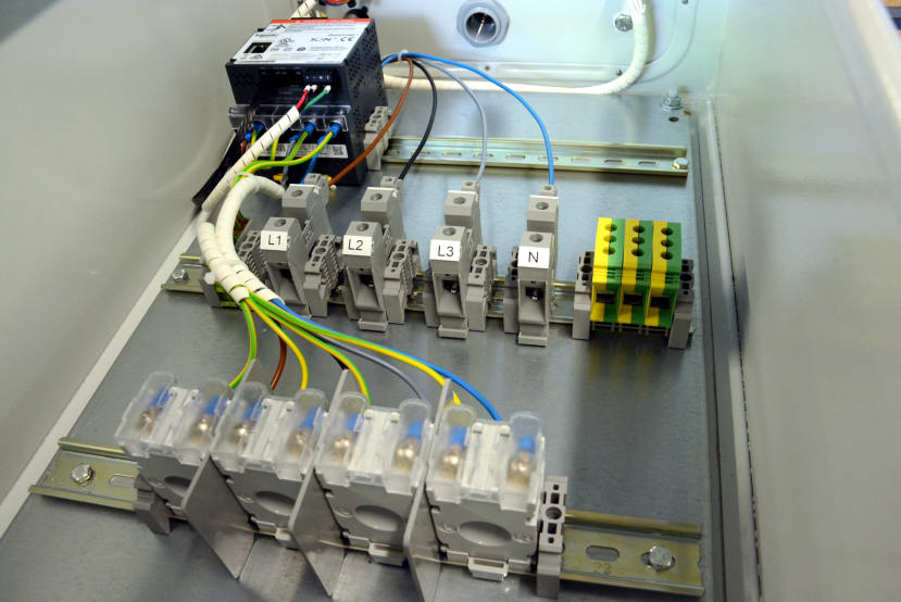
The current transformers (CTs) shown above will have cables fed through with energy flowing from the top downwards, which is in via the transformer face labelled P1 and then out P2.
Partition plates were inserted between the CTs simply because we had some and the thought being that at least some amount of separation may help reduce crosstalk. No recommendations were found for spacing and it’s possible that ideally they might be spaced further apart, but in our case, this would then result in L1 having to route around the PM8000 meter, which would be best avoided.
CTs must always have their output terminals shorted, otherwise excessively high voltages may develop in their secondaries, resulting in insulation breakdown and damage, plus an increased risk of electric shock. It is also common practice for all the S2 terminals to be connected to ground. This is frequently done by looping ground across the aforementioned terminals.
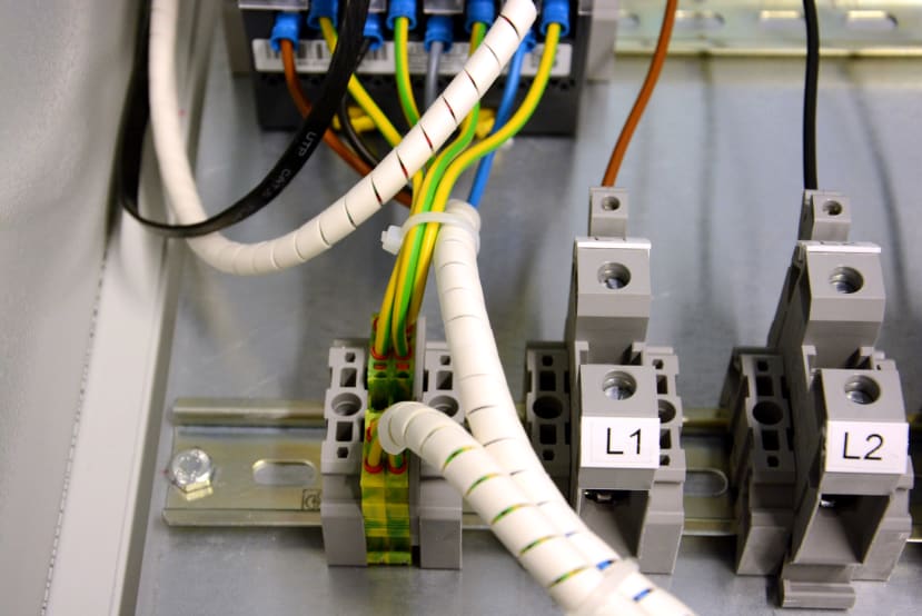
However, in this case, it was decided to run individual ground connections to bridged terminals. The PM8000 I1-I4 terminals were then connected to the ground terminals and CT S1 terminals.
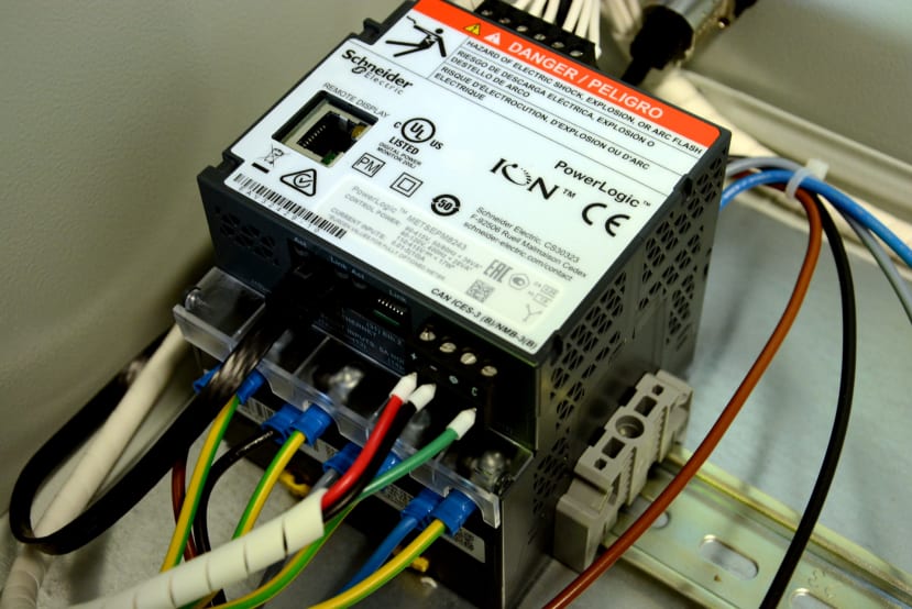
Above can be seen the PM8000 with RS-485 connections top-right, Ethernet to the left, and current measurement CT connections below. On the opposite side are the digital I/O connections and voltage measurement terminals. The RJ45 connection in the top is for the remote display.

Digital I/O cabling was soldered to a Binder 720 connector, with Hellermann sleeving. Similar with the RS-485 connections.
Next steps
In the second and concluding part of this series, we will connect control power, together with a 3-phase power supply and load, following which carry out configuration and demonstrate basic use.