Lighten the Load
Follow article
 Dave from DesignSpark
How do you feel about this article? Help us to provide better content for you.
Dave from DesignSpark
Thank you! Your feedback has been received.
Dave from DesignSpark
There was a problem submitting your feedback, please try again later.
Dave from DesignSpark
What do you think of this article?

This project shows how to use a Raspberry Pi and a couple of potentiometers to control a load – controlling the brightness and blink speed of some DC incandescent light bulbs. This project builds on my Steampunk Advertising Sign project.
An analogue to digital converter is used to translate the readings from the potentiometers into something the Raspberry Pi can use. PWM on the Raspberry Pi GPIO pins is used to trigger Open Collector Drivers which control the bulbs.
This project is broken down into seven steps:
- Connect one bulb to the Pi and switch it on and off using Node-RED and PWM
- Connect the potentiometers to the Pi
- Install the Node-RED analogue to digital converter (MCP3008) node
- Write the Node-RED flow for the potentiometers
- Write the Node-RED flow to control the bulb using the potentiometers
- Write the Node-RED flow to control all the bulbs
- Make a circuit board to combine seven Open Collector Drivers and an analogue to digital converter
Pre-requisite skills
- Soldering skills
- Knowledge of Node-RED programming
(NOTE: You can find two simple Node-RED projects in the free to download MagPi magazine, 'Cheerlights Orb' in MagPi magazine Issue 41, pp58-59 and 'WakeDino' in Issue 47, pp 44-45)
Parts
- Raspberry Pi, power supply, cables, SD card (123-7157)
- 2 off Potentiometer (041-0205)
- 7 off Darlington Pair NPN (545-0078)
- 2 off 10way PCB vertical mount terminal (220-4355)
- Single sided stripboard (043-3826)
- Microchip MCP3008-I/P (669-6064)
- 7 off IN4001 Diode (628-8931)
- Header 40 way, 2 row (668-9684)
- GPIO Ribbon cable https://www.adafruit.com/product/1988
- 2 off knob for the potentiometer (022-3742)
- 8 off 2-way terminal blocks
- 10 off 1k Resistor
- Gold spray paint
- Hot melt glue
- Wires
- Advertising Sign and Power Supply (as per Steampunk Advertising Sign project)
Step 1 – Connect one bulb
In the Steampunk Advertising Sign project, I used 24V 25W DC incandescent bulbs. As each was wired individually they can be controlled individually. The Raspberry Pi GPIO pins only provide a signal of 3V3 and so cannot switch the bulbs directly. However, an open collector driver (Thingatron) can be used. If every one of the fourteen bulbs is to be controlled separately, fourteen Thingatrons would be required. As projects get more complex, more likelihood for errors creep in. Therefore this project starts with just one bulb – for now this can be done on a breadboard. Using a breadboard for electronics is great for prototyping and making sure something works, but for a more robust solution, solder the components on to stripboard or Veroboard or even a custom-designed PCB.
WARNING – Use 1k ohm resistors at the base of the Darlington Pairs – see footnote*
- Connect a Darlington Pair, diode, resistor, the DC power supply for the bulb and the lampholder together, as in Figure 2, below. Connect the resistor to the physical Pin 3 on the Raspberry Pi.
- Connect the Pi to a monitor and keyboard and open Node-RED (Find it under Programming, Node-RED).
- Drag a GPIO output node, and set it to Pin 3, Type PWM output. Name it Lamp 1.
- Drag an inject node on to the flow, change the payload to a string and type in 100.
- Drag another inject node on to the flow, change the payload to a string and type in 50.
- Drag another inject node on to the flow, change the payload to a string and type in 0.
- Connect all three inject nodes to the GPIO output node. Click the red “Deploy” button at the top right.
- Click on the different inject nodes. These should turn the lamp on full brightness, on half brightness or off.

Figure 1
Step 2 – Connect the potentiometers to the Pi
- Switch off the Pi and the DC power supply.
- Connect the MCP3008 analogue to digital converter and resistors to the circuit, as in Figure 2, below. The datasheet for the MCP3008 gives a diagram of which leg of the chip is which. There will be an indentation or ink blob on the chip to mark the end where Pin 1 is.
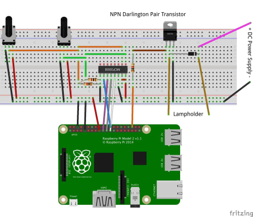
Figure 2
| MCP3008 (Pin) | Wire Colour | GPIO Physical Pin | Other |
| VDD (16) | Red | 1 (3V3) | MCP3008 VRef (15) |
| VRef (15) | Red | 1 (3V3) | n/a |
| AGND (14) | Black | 6 (GND) | n/a |
| CLK (13) | White | 23 | n/a |
| DOut (12) | Grey | 21 | n/a |
| Din (11) | Purple | 19 | n/a |
| CS/SHDN (10) | Blue | 24 | n/a |
| DGND (9) | Black | 4 (GND) | Resistor |
| CH0 (1) | Green | n/a | Potentiometer1 and Resistor |
| CH1 (2) | Orange | n/a | Potentiometer2 and Resistor |
The potentiometer is wired:
1 to ground
2 to the Channel required on the MCP3008
3 to 3V3
Step 3 – Install the node-red-node-pi-mcp3008 node
To be able to read from the Analogue to Digital converter, we need a special Node-RED node. Fortunately, one is already made, but it is not in the default palette. We can install the node-red-node-pi-mcp3008 node using the “manage palette” option in Node-RED:-
- Power the Pi back on, but leave the DC supply switched off
- Check the prerequisites on the website: https://flows.nodered.org/node/node-red-dashboard. As at September 2017, this means we need to enable the SPI on the Raspberry Pi using raspi-config from the command line as follows:
Run “sudo raspi-config”
Select 5 - Interfacing Options
Select P4 - SPI
Select yes to enable SPI
Select OK to confi
Select the Finish button
Then open Node-RED and click:
Menu
Manage Palette
“Install” tab.
In the box next to the magnifying glass, search for “node-red-node-pi-mcp3008”. Click the small “install” button to the right of the “node-red-node-pi-mcp3008” selection. Follow the on-screen instructions.
The node will now appear in the node menu palette in the “Raspberry Pi” section as “A/D Converter”.
Step 4 – Write the Node-RED flow for the potentiometers
- Drag into your flow an inject node and an A/D converter node and connect them together. Connect a debug node to the output side of the A/D converter node.
- Double click the inject node, change the payload to type “string” and put a 0 in the payload box. This is to tell the A/D converter node to look at Channel 0 on the MCP8003 chip.
- Change the “Repeat” from “none” to “interval” and change the interval to “every 5 seconds”. This means we will get a reading from the potentiometer every five seconds.
- Tick the “inject once at start” button and click “Done”
- Double click the A/D converter node and change the Input pin to “A0”. The Device ID should be CE0. Click “Done”.
- Click the “Debug” tab on the right-hand side (under the Deploy button)
- Click deploy - a number should appear every five seconds. This will be a number between 0 and 1023, depending on how far the potentiometer is twisted.
- Repeat steps 1-7, and this time change the Channel to 1. You should now be able to see the output of both potentiometers.

Figure 3
Step 5 – Write the Node-RED flow to control the bulb using the potentiometers
We can quite simply control the time the bulb is on or off using the potentiometer. We can also quite simply control the brightness. However, to get the time delay AND the brightness to effect the same bulb at the same time requires a function node to store the values (This part is based on work by Andy Stanford-Clark – with thanks!).
Rather than a step by step guide here, I have put the flow on Github as Step E Flow.rtf which you can import into your own Node-RED. (Copy the text document to the clipboard, then in Node-RED click Menu, import, clipboard and paste it in.)
Step 6 – Write the Node-RED flow to control all the bulbs
This step can be done before all the bulbs are connected!
I decided to double up the bulbs per input – so two bulbs are triggered on one GPIO input. This makes the Node-RED flow simpler. Using the flow used in Step E as the basis, my final flow is also in Github AdvertisingSignTotalFlow.rtf, which again, you are free to paste into your Node-RED and adapt however you like. I am sure you can have fun with the sequences – you could even write a function node with an array to do this.
Take care that you don’t have another tab with the same GPIO pin used – as this can give spurious results.
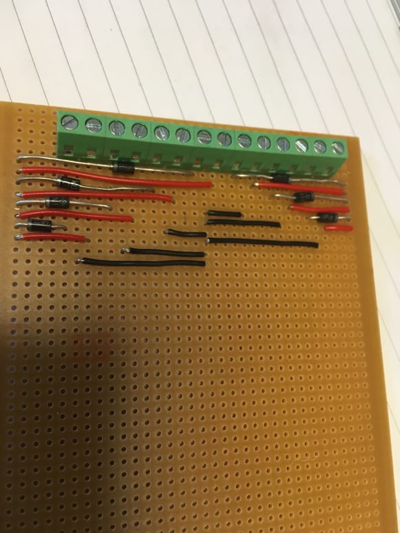
Step 7 – Make the circuit board
So far this you may have been done all this on a breadboard, and with only one lamp (the flows have used GPIO pins that were not yet connected to Open Collector Drivers).
To make everything more robust, it needs to be soldered together on single sided stripboard, Veroboard or similar. The design of this is up to you – Below are a series of photos of my efforts. I use screw terminals where possible and a ribbon cable so I can connect the Pi easily.
| GPIO Physical Pins | Item |
| 35 | Lamp 1 |
| 15 | Lamp 2 |
| 13 | Lamp 3 |
| 11 | Lamp 4 |
| 7 | Lamp 5 |
| 5 | Lamp 6 |
| 3 | Lamp 7 |
| 24 | MCP3008 Pin 10 |
| 19 | MCP3008 Pin 11 |
| 21 | MCP3008 Pin 12 |
| 23 | MCP3008 Pin 13 |
| GND | MCP3008 15 |
| 3V3 | MCP3008 15 and 16 |


Things I wish I had known before making the circuit
- Use a small tip on the soldering iron
- Triple check BEFORE breaking any tracks on the stripboard
- Check for shorts using a continuity tester (on a multimeter) BEFORE connecting a Pi
(I fried one)
Darlington Pairs are required. Using "normal" transistors is a bad idea (see image below and Footnote 2).
It is recommended that the Raspberry Pi GPIO pins are used with a maximum of 16mA per pin, and a total of 100mA (0.1A) for all the pins. The Thingatrons use 330R resistors to the base of the Darlington Pair. Using 14 of these would give a total of 0.14A.
V/R = I
3.3/330 =0.01A
14*0.01 = 0.14A
By increasing the resistor size to 1000 ohms, we can reduce this to 0.0462A
V/R = I
3.3/1000 = 0.0033A
14* 0.0033 =0.0462A
Footnote 2:
In a transistor, the current of the Load is limited (in the case of NPN Transistor – BC337 to a maximum of 800mA). So if the current it draws is too high it would fry the transistor. Or make it explode (see above photo!). However, a Darlington pair uses two transistors that act as a single transistor but with a much higher current gain – and the current limit should not be a problem.
Comments