Summer Sounds - Building a 12 Volt Sound System for Outdoor Use Part 3: Amplification and the Finishing Touches.
Follow article
 Dave from DesignSpark
How do you feel about this article? Help us to provide better content for you.
Dave from DesignSpark
Thank you! Your feedback has been received.
Dave from DesignSpark
There was a problem submitting your feedback, please try again later.
Dave from DesignSpark
What do you think of this article?
Audio path and DC wiring, adding a voltage regulator, and testing.
Introduction
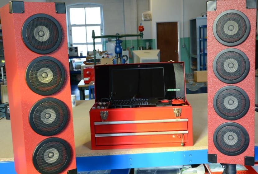
In parts one and two of this series of blogs I set out my plans to create a stylish, great sounding 12 Volt sound system to accompany my DJ System in a red toolbox. As can be seen in Part 2, the speakers certainly looked the part, now it was time to get them sounding good too.
A balancing act
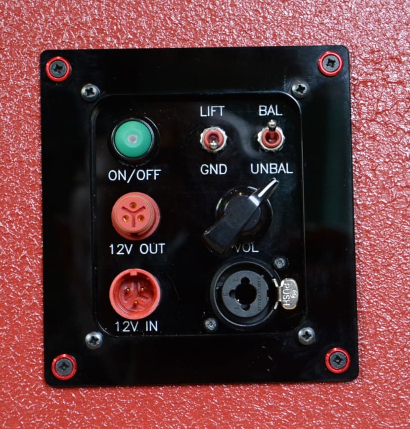
I wanted a choice of balanced and unbalanced audio inputs. The sound card I use for DJ’ing has balanced outputs so it would be good to be able to take advantage of the superior signal quality. Unbalanced input would be a sensible addition so that I could plug a ’phone or even a cassette player into the system without problems. (Cassettes are, apparently, making a come back).
Amplification
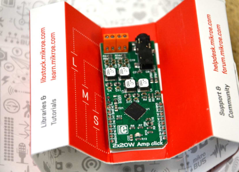
At the heart of the amplification of this system is a Mikroelectronica ClickBoard (165-1405) and a Class D Stereo Amplifier that, as I was to discover, produced a very healthy 2x20W. Each stereo channel would power two of the Fostex full range speakers installed in the cabinets.
Putting it together
The choice of inputs was going to make things slightly more complicated – the circuit would need to include an audio isolation transformer or “balun”
(123-7201)
for the balanced input and I had to do some internet research to work out how to connect it all up.
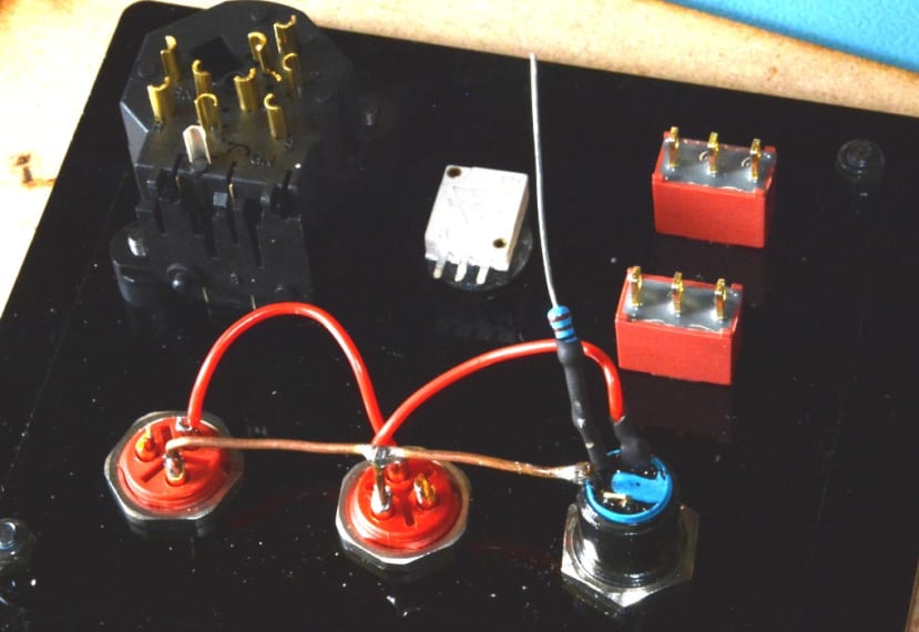
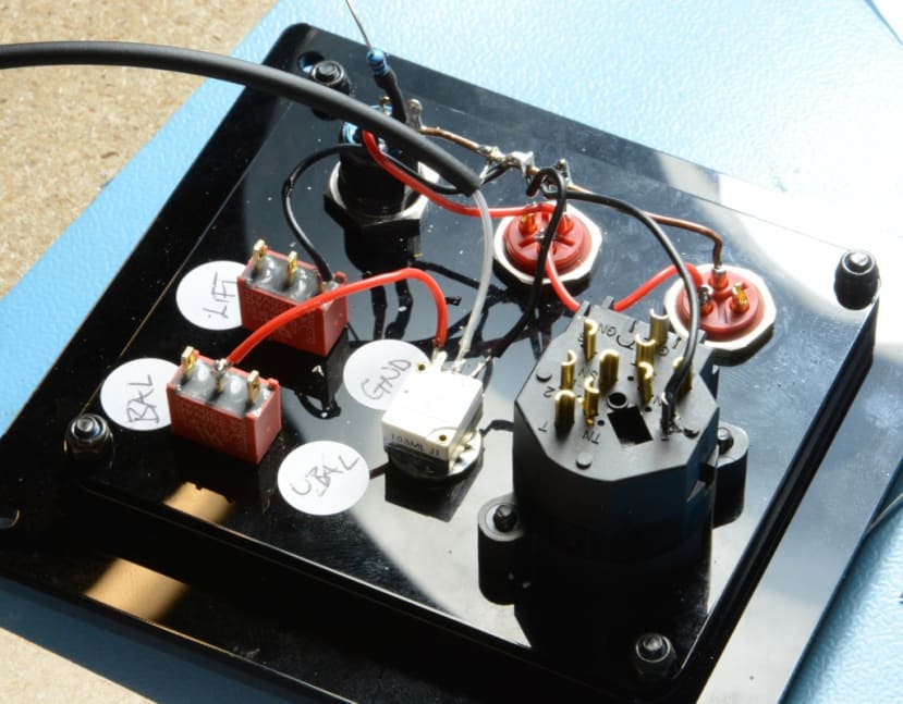
The amplifiers themselves, along with the transformers, were to be mounted on stripboard (100-4328) which in turn would be fitted to a piece of laser-cut MDF screwed to the inside of the back panel of the speaker cabinets. The wire connecting this to the controls and sockets which are mounted on a control panel in recesses in the back of the cabinets were to be routed through the slot I detailed making in Part 1. The eagle-eyed amongst you will have noticed that the control panels now have the addition of a ground lift switch so they had to be re-cut and the wax lettering re-applied.
Once I was happy I knew how everything was going to be connected, I made a start.
A little hiccup
Having got everything soldered together it was time to give it a test run before installing it in the cabinets themselves. This is where I hit a little problem. Having plugged in my ‘phone’s audio and started playing one of my mixes, I was greeted by a resounding silence. I re-read the information on the amplifier on Mikroe website and realised that, in addition to the 12V to drive the Amplifier circuit, I needed 3.3V to power the board logic.


Fitting the Amplifiers in the Cabinets

I added some remaining pieces of acoustic foam to the inside of the cabinets and then fitted the back panels. They were a really tight fit which made it quite difficult but this means they are airtight which will make for a better acoustic performance.
I just needed to make up the lead that took the 12V from the speaker connected to the power supply to its partner. I used Binder 720 series connectors (734-5492) as I have throughout this and related projects, since they are IP67 rated, always feel well made, provide a good snap-in connection and they come in red.
Now it was time to connect the new sound system up to the Red Tin and see how it sounded. The combination of the 4 full range speakers and the class D Amplifier provided a really punchy and surprisingly loud, sound. Tweaking the equaliser in the Red Tin produced a good bass response too.
Final tweaks
I plan on making a few final tweaks. I think some carrying handles would be a good addition, I just need to find the right ones. The control panel would benefit from being recessed a little further to help protect the switches. Speaking of which I also need to fix the 2 toggle switches so they are fastened to the panel correctly – that will teach me to always read the datasheet even on things as seemingly straightforward as a toggle switch (734-6968) .
Now to take it out ...
I have thoroughly enjoyed this project, as I pointed out initially it has put my DIY skills to the test and, as ever, furthered my knowledge of electronics. The sound system itself has exceeded my expectations both in looks (the red paint has a lot to do with that) and the sound. I am itching to take it out and show it off now.
By the way, the music in the video is by Churn Milk Joan and is called “Sylvia Plath on a Bike” after some mysterious graffiti that appeared on a pub wall in my local town just prior to the Tour de France visit to Yorkshire. You can find it to download on Bandcamp if you like what you hear.