High Frequency Relays for High-speed Differential Transmission Signal Switching
Follow article
 Dave from DesignSpark
How do you feel about this article? Help us to provide better content for you.
Dave from DesignSpark
Thank you! Your feedback has been received.
Dave from DesignSpark
There was a problem submitting your feedback, please try again later.
Dave from DesignSpark
What do you think of this article?
Overview
In recent years, various devices have been generating, transmitting, and processing a large amount of information data, such as high quality images, movies from digital cameras and smart phones transmitting through internet, television, etc.
There are several standards for digital transmission, such as HDMI, USB, MIPI, DDR, Thunderbolt, PCI Express, SATA (Serial ATA), so high speed signals exceeding the bandwidth of several Gbps are often required even for general use. (Figure 1)
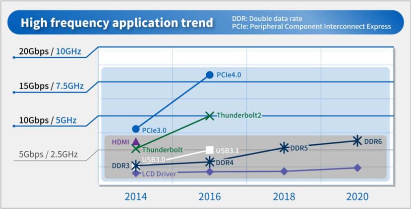
Figure 1
This high speed signal is widely used not only for communication between devices but also for processing equipment internal circuits, communication between built-in parts, as well as for inspection machine at the manufacturing stage of equipments and parts.
Mechanical relays are built in the main bodies of production and inspection equipment and final products, and are used for switching signal connection.
In the case of transmission and switching of high speed signals by means of mechanical relays, change and deterioration of the signal waveform due to the transmission characteristic (frequency characteristic) of the relay used affects the signal quality, so that a relay having better transmission characteristics is required.
G6K-RF is a relay with excellent transmission quality developed for high speed signals, especially for high speed differential transmission signals.
On high speed differential transmission systems
The differences between differential transmission system used for high speed signal transmission and single end system used in conventional signal are the following:
In the single-end system, a signal is transmitted with one line, and the magnitude of the signal is determined by the potential difference with the ground.
On the other hand, in the differential transmission method, opposite phase signals are transmitted to the two lines, respectively, and the magnitude of the signal is determined by the potential difference between the two lines. (Figure 2)
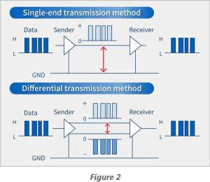
In the single-end method, since a single signal line transmits a signal, there is the advantage that the number of signal lines is small, but it is susceptible to the influence of external noise and there is a limit in speeding up.
Therefore, in order to transmit a large amount of signals quickly, it is necessary to increase the number of signal lines and to perform parallel transmission and to consider synchronism between parallel signals, and it is rarely used for high-speed signal applications.
On the other hand, in the differential transmission method, it is the greatest advantage is that it is resistant to noise in order to see the potential difference between the two signal lines. Normally, since external noise is similarly applied to two signal lines, noise is cancelled out when viewed by a potential difference at the time of reception. (Figure 3)
Also, being resistant to noise means that the voltage amplitude of the signal can be kept low, so it is possible to shorten the rise/fall time of the signal and to increase the speed. (Figure 4)


In the high-speed differential transmission system, the specification required for the mechanical relay is a two-pole contact type for transmitting signals on two lines, a signal is transmitted by a potential difference between the two signal lines, so that a one-pole contact side And the transmission characteristics on the 2 pole contact side are equivalent. In circuit switching applications, it is also said that the transmission characteristics on the N.O contact side and the N.C contact side are equivalent.
Representative circuit example of relay
Main applications of relays used in semiconductor inspection apparatuses include signal switching between the main body of the inspection apparatus and the inspection object, switching of input / output channels of the apparatus, and the like. Specific circuit examples are shown below.
- Input and switch different signals to the inspection object.
- Switch inputs and outputs of signals to a plurality of inspection objects and inspection device channels.
- Switching between signal from inspection equipment and loopback test
Evaluation of high-speed differential transmission signal
In digital signals, "1" and "0" changes in a complicated manner, so it is not possible to evaluate the quality of the waveform from a single frequency signal.
For that reason, what is commonly referred to as eye pattern/eye diagram (obtained by sampling a signal waveform in a relatively long time or displaying a prescribed pattern signal such as a random signal) in superimposition is generally used. It is called an eye pattern because the image on which the waveform is superimposed looks like an eye. (Figure 5)

The vertical axis of the eye pattern image is voltage amplitude and the horizontal axis is time. When the voltage amplitude varies, the upper and lower lines are dthick, and in the case of attenuation, the upper and lower widths become narrow.
When there is variation in the time axis direction, the width of the line that transits from the top to the bottom or from the bottom to the top increases.
When the opening (the part where the eye is open) is wide, it can be said that the signal quality is good because the signal can be read correctly. If it is narrow, the signal can not be read correctly or an error occurs and the signal quality deteriorates.
Eye pattern characteristics are important for relays used for differential transmission signals, but the specifications required for relays are generally different depending on the application.
Items for consideration during evaluation of customer application and clearance of final system include: Transmission / reception unit, characteristics of the whole transmission path such as cable, connector, device and interface standard (USB, HDMI, MIPI, etc.) It is common practice to ensure that the specifications of relays match the load requirements.
Product structure outline (Characteristic of structure principle)
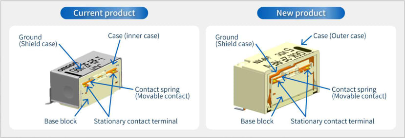
The existing G6K-RF series has the basic structure of a signal relay with good frequency characteristics with a metal case.
By shielding with a metal case and grounding, high frequency characteristics were improved by configuring a microstrip line structure in which a space between a metal case, a resin case and a signal terminal is used for a high frequency transmission line.
However, in this structure, there are restrictions such as the thickness of the resin case inside the signal relay, the spacing between the signal terminals and the metal case, and there is also a limit to making ideal transmission path characteristics.
In the new product of this time, by making the shape and dimensions of the metal case aiming at the optimum characteristic impedance for each part of the signal terminal of the built-in relay, it was possible to improve to the more excellent frequency characteristic. (Figure 6)
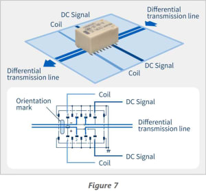
Feature 1: high-speed transmission signal related characteristics
Offering stable linearity high insertion loss characteristic at 3 dB or less from DC to 8 GHz. (Figure 7)
Feature 2: Others
- Allows for pattern wiring underneath the relay.
In existing hight frequency relays, there are some points of connection on the board with the bottom of the relay such as GND, and some patterns can not be placed underneath the relay because they interfere with the signal line inside the relay.
In order to avoid this, it was necessary to design complicated wirings using multilayer boards and sacrificing differential transmission characteristics in circuit design. However, with this product, since it allows for pattern underneath the relay, it contributes to a simple circuit design with good high frequency characteristics. (Figure 8)
- Plastic case does not interfere with PCB board traces

- Outside L-shaped surface mount terminal
By making the terminal shape an outer L shape and the same dimensions, we have achieved excellent solderability and improved visibility of the soldered state at the appearance inspection.
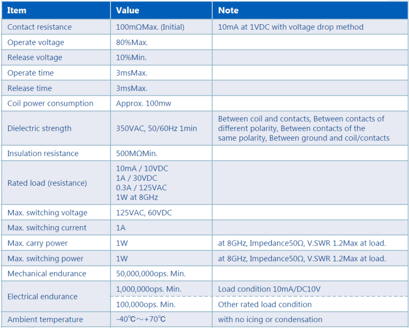
- Main ratings, characteristics, specifications
Afterword
The use of high-speed transmission signals is expected to further increase the demand for higher speed and signal transmission quality in the future due to the expansion of applications and fields such as digitalization of various equipment and household appliances and increasing the amount of signal information and IoT.
We believe that this relay can be widely deployed in semiconductor inspection equipment, manufacturing equipment and related equipment used in these devices.