A First Look at the Infineon EVALICB2FL03GTOBO1 Evaluation Board
Follow article
 Dave from DesignSpark
How do you feel about this article? Help us to provide better content for you.
Dave from DesignSpark
Thank you! Your feedback has been received.
Dave from DesignSpark
There was a problem submitting your feedback, please try again later.
Dave from DesignSpark
What do you think of this article?
Infineon controller IC provides a smart solution for driving UV-C germicidal tubes.
Introduction
In this article we’ll be taking a look at fluorescent tube technology and how they work, how they are are started and driven, and then the Infineon EVALICB2FL03GTOBO1 evaluation board that features the ICB2FL03G smart ballast controller IC.
Driving a Fluorescent Lamp
Fluorescent lamps are an interesting beast to control due to their inherent characteristics; requiring filament preheating before starting, and a negative resistance once ignited - and also some interesting end-of-life failure modes. To prolong the lifespan of a lamp, a controller needs to be able to start the lamp in a controlled manner that extends the filament lifespan, and then carefully monitor and control the operating conditions including watching for various conditions that signal the lamp end-of-life such as the rectifier effect.
A ballast is required to drive a fluorescent lamp due to its negative resistance once the arc discharge is initiated; if no ballast is used the lamp can self-destruct rapidly due to a large current (well beyond the design current of the lamp) being able to pass.

This dictates the requirement of having a ballast that serves to limit the current through the lamp. Typically, these were a large inductor in series with the incoming AC supply and the inductance dictates the current limit; meaning that the ballast differs between lamp wattages and additionally the AC supply frequency.
More modern installations tend to use electronic ballasts that rely on a control circuit to regulate the current flow — these also have a higher efficiency compared to a magnetic ballast.
Fluorescent lamps also require a starting circuit to “strike” the arc discharge across the tube. This used to be done using a thermal starter (utilising a bi-metallic switch and glow discharge tube), often referred to as a “glow switch starter”, to warm the lamp filaments and then generate a high voltage pulse when the starter contacts are opened. The generated high voltage pulse is then sufficient to strike the arc, and then the lamp current is limited by the ballast.
Sometimes this starting process may take a few cycles if the lamp filaments are not sufficiently heated, and on lamps that have reached end-of-life it may continue until either a filament burns out or a starter contact burns out.
Typically, most fixtures now use electronic starters that are either compatible with plug-in starters or are integrated into an electronic ballast in the luminaire. Electronic ballasts have features for protecting and prolonging the lifespan of a lamp; including overload protection, EOL detection through the rectifier effect, support for restarting a lamp with skipped preheating, and automatic restarting should the lamp fail to remain lit.
The Hardware
Evaluation Board
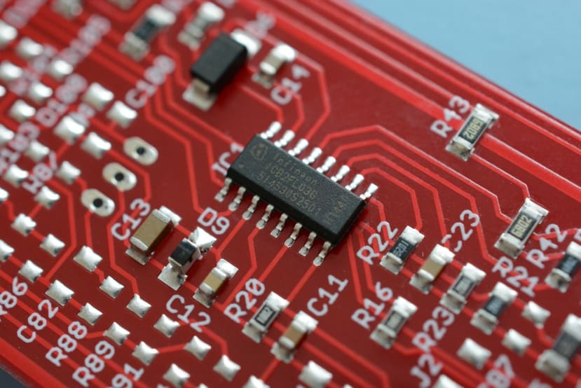
The EVALICB2FL03GTOBO1 evaluation board (222-6958) features the Infineon ICB2FL03G smart ballast controller that is specifically aimed at UV-C disinfection lamps. Included on the evaluation board are all the supporting components to drive a UV-C lamp, including inductors to provide Power Factor Correction and the boost converter to drive the lamp.

The ICB2FL03G controller features PFC to provide a high power factor, important for offices and buildings with large energy supplies as providers often penalise large consumers for poor power factor. Soft switching is also implemented within the controller to minimise EMI produced by the circuit, whilst still providing an efficiency figure of over 90%.
Multiple lamps are also supported in a series connection, and a choice of either voltage or current control modes are provided — voltage control for supporting multiple different lamp types, and current mode for a lower component count and BoM cost.

Another feature of the ICB2FL03G is that the lamp is driven with a high-frequency, in the case of the evaluation board setup 45kHz, AC waveform which improves the operational efficiency of the lamp; above what can be obtained with a standard inductive ballast.
Reference Design Specifications
Given the high integration level of the controller, a minimal BoM part count is required — a small number of passives such as resistors, capacitors and diodes; plus inductors and three MOSFETs are required to construct the ballast circuit. Various operating parameters of the chip including the run frequency, preheat frequency and preheat time are all set via resistors; reducing the need for complex external circuitry.
The board as designed will accept a 180-270VAC input, with an input current of 257mA. A 54W lamp is designed to be connected to the board, however, it can also be run with a 55W lamp.
Thanks to the PFC front-end, total harmonic distortion presented to the AC input is sub-4%, and a power factor better than 0.99 under normal operating conditions, and efficiency of over 90%.
Board Operation
Startup of the ballast board includes multiple stages before the fluorescent tube is lit and operating normally, all of which are carefully managed by the control IC.
The first step is bringing the controller out of the “UVLO” state. This occurs when the AC input is initially applied, and the supply voltage at the controller input rises until 10.6V is reached — at which point an internal current source is activated and filament detection begins.
Filament detection ensures a lamp is installed in the socket, and that it is in a condition suitable for starting. Broken filaments mean that a lamp cannot be started, and likewise if the ballast tries to start a nonexistent lamp there is a potential for a high-voltage shock from the bare lamp socket contacts. With lamp filament detection completed, the controller then moves to start up the PFC circuit and inverter circuit that drives the lamp.
In the inverter & PFC startup, the high voltage bus is monitored to ensure it remains between 12.5% and 105% of the normal range. If this condition is met, the inverter then starts running to bring the DC bus voltage up to the nominal voltage — once this hits the 95% of nominal mark the PFC section begins running, ensuring a clean current consumption from the AC supply.
Soft start is then entered, to gently begin starting the tube. This consists of the controller reducing the inverter switching frequency towards the preheating frequency; at which point a large current should flow through the lamp filaments, and a low voltage is developed across the lamp itself. As the preheating frequency is achieved, a timeout begins that expires at the period set by the external resistor “RTPH”.
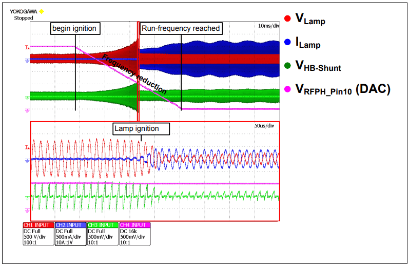
Once the timer expires, the controller moves onto the ignition phase — the inverter frequency again begins dropping from the set preheat value towards the run frequency. At some point in this process, the voltage generated across the lamp will be large enough to ignite the arc discharge. At this point the controller moves to a pre-run phase which only lasts for a short period, to avoid the control system within the IC malfunctioning due to the lamp conditions having not stabilised yet.
In this phase, the ignition regulator on the controller is still running to reignite the lamp should it extinguish or show poor ignition behaviour. Not all protection features of the controller are operational at this point, to allow the lamp to stabilise. After this phase has been completed, the controller then moves to run mode — this includes all the lamp protection measures being enabled.
At this point, the lamp is running normally, and the controller will remain in this phase unless the lamp is turned off, or a fault condition occurs.
Lamp and Ballast Protection Features
The ICB2FL03G features a battery of failure detection modes, including surge protection, inverter & PFC overcurrent, bus over- and under-voltage protection, lamp EOL detection in four different ways, capacitive load detection, and finally emergency detection.

Surge detection aims to protect the lamp and control circuit from potentially damaging AC supply surges. This is monitored by watching for a DC bus overvoltage event, followed by an inverter overcurrent. Once this occurs, the lamp is shut off and then restarted (including a preheating delay), protecting both the MOSFET devices within the ballast circuitry and the lamp itself.
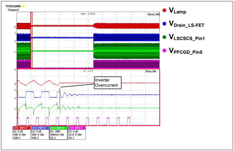
Inverter overcurrent aims to protect the ballast from damaging overcurrent situations. The first overcurrent event triggers a 40 second timeout period, and a restart of the controller which reignites the lamp. Should a second overcurrent event happen in this period the controller latches the fault, requiring either a lamp reinsertion or AC power reapplication to reset.
PFC overcurrent protects the PFC stage from overload, but is implemented in a way that does not affect the operation of the ballast should an inductor overcurrent situation arise. Due to the way the circuit is constructed, turning off the PFC MOSFETs on a cycle-by-cycle basis does not stop the lamp from operating, and thus is not regarded as an operational fault.

Bus overvoltage is caused due to the PFC start-up, and a small overshoot to 109% of nominal bus voltage is permitted. When this happens, the PFC gate drive is turned off until the bus voltage drops to 105% of nominal, and providing this happens within 625 milliseconds the controller will reactivate the gate drive and carry on. Should the bus voltage not drop, the controller will power off for protection.

Bus undervoltage is tied into the emergency detection mode, which is implemented to comply with the VDE 0108 standard. This dictates that illumination of the lamp returns after a brief input voltage interruption. Provided the bus voltage is above a certain value, and the input voltage is lost then returns the lamp can be reignited without having to undergo a preheating cycle — reducing the time for illumination to return.
Lamp end-of-life detection is implemented by checking for “EOL1”, which is a lamp overcurrent situation and can signal the end of the lamp life, at which point the controller switches off. Fluorescent tubes can exhibit a phenomenon called “rectifier effect” (referred to as “EOL2” within the controller application note) where the lamp begins to rectify the AC current, concentrating heat on one of the cathodes which can lead to damage to the lamp or fixture. Finally, the last two EOL modes are the “switched-rectifier effect” and “hard rectifier effect”, both of which trigger an EOL1 condition within the controller. Littelfuse has a good application note that details what the rectifier effect is, and how it is damaging.
Capacitive mode detection is primarily used when the lamp is operated in current mode preheating, where removing the lamp (or a cathode breaking) exposes the snubber capacitor to being charged and discharged directly by the MOSFET, with the potential to cause damage. If an overcurrent situation arises in capacitive mode detection, the controller switches off to protect the circuit from damage — this can only happen in designs where the run frequency of the ballast is below the resonance frequency of the unloaded resonant circuit that drives the lamp.
Circuit Design
Infineon have provided a detailed application note, and accompanying spreadsheets that help reduce the complexity of designing a ballast around the ICB2FL03G controller. The application note also walks through the operation modes of the controller in greater detail, and the theory of operation.
Summary
In this post, we have taken a look at fluorescent lamps and how they are driven, and finally the Infineon EVALICB2FL03GTOBO1 evaluation board for the ICB2FL03G UV-C smart ballast controller.
The Infineon ICB2FL03G controller is packed full to the brim with features for managing a UV-C germicidal lamp, including intelligent preheating, a high efficiency when running thanks to the high-frequency inverter, low EMI emissions, a PFC stage to ensure a good AC supply power factor, various lamp failure detection modes, and compliance with the VDE 0108 standard for emergency lighting.
Infineon has also provided a solid reference board with accompanying documentation to reduce the time to market for custom ballast designs, with a detailed walk-through of the component selection process to help ease the design process.
Comments