A DIY Antenna Measurement System Part 2: Mechanical Prototyping
Follow article
 Dave from DesignSpark
How do you feel about this article? Help us to provide better content for you.
Dave from DesignSpark
Thank you! Your feedback has been received.
Dave from DesignSpark
There was a problem submitting your feedback, please try again later.
Dave from DesignSpark
What do you think of this article?

Integrating an ebm-papst EC motor with a RevPi Core for control, and a LimeSDR Mini for signal generation and reception, to create a system that measures antenna performance.
View the new range of K4 drive system development kits as previewed by DesignSpark here

This series of posts follows the progress of the design and build of a low-cost system that is based heavily upon the Enhanced Machine Controller Antenna Range (EMCAR) open source project. In Part 1 we introduced the project and in this post, we will cover mechanical design and prototyping.
Enclosure design

We wanted to build an enclosure that would be suitably sturdy, provide a good solid mount for the motor and turntable, and would have plenty of room for the associated electronics.
It was decided to construct a frame from 30 x 30 Aluminium Extrusion (761-3284) . In the past, I had used a similar construction technique for other projects, such as the demonstration units for the RS stand at Electronica, which used the 20 x 20 extrusion. I was confident that the larger extrusion would provide a solid support for the motor and whatever antenna we mounted on it.

I sketched out an initial design, making sure there would be plenty of room to house all the parts without it being too cramped. The size of the turntable was governed to some extent by the fact that I would be cutting prototype parts on a laser cutter that could handle a maximum of 600mm x 400 mm. I settled on a suitable size and calculated how much of the extrusion we would need.
Building the aluminium frame

the aluminium lengths had been delivered I carefully measured and cut them – remembering the old adage, “measure twice and cut once”.
The band saw used for the cutting is accurate and fast but it does leave some swarf, so the ends of each length needed to be tidied up with a fine file.

Once the pieces were cut I could start to assemble the frame. As can be seen in the picture below, the frame is held together by 90-degree connector brackets (767-5566) .

Although the upright can be held in place with a single bracket, I decided for extra strength I would use two.

This should make the enclosure “bomb proof” and allow us to support a heavy load on the turntable without fear of it going out of shape or even collapsing.
The ebm-papst Motor and Gearhead

The K4 Drive System Development Kit we had taken delivery of included a K4 Variodrive Compact motor with a crown gearhead.
ebm-papst produce a selection of motors and associated gearboxes that come in all sorts of different combinations. The unit we are using here is the VDC-49.15-K4 motor that runs on 24V DC and has a speed of 6000 rpm at no-load operation and a nominal output power of up to 99 W.

The matched gearbox is the EtaCrown Plus 63 that has a rated output torque of 40.0 Nm. Its shaft features a standard DIN 6885 5x5x20 Feather key which will provide keyed joint to secure the turntable hub, as can be seen later in this blog post.
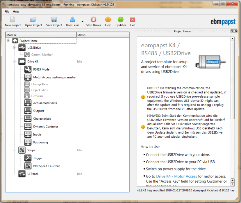
The motor features completely integrated operating electronics, which in practice means you can connect it to a PC running the ebm-papst Kickstart software via the RS485 interface and control the speed, torque, and position of the motor as well as monitoring its performance.
The Kickstart software can be downloaded from the ebm-papst web site at the foot of this page.
Fitting the motor and turntable

The top panel was cut from 2 pieces of 5mm MDF as it is slightly larger than the laser cutter can handle in one piece. It supports the motor and a “lazy Susan” bearing sits between this and the turntable. The motor is mounted diagonally beneath the top panel to give some extra clearance.

A boss cut from two pieces of 5mm MDF is fixed to the underside of the turntable and provides a secure fitting for the motor shaft and keyway.
The turntable is then fitted to the top by fastening the inner ring of the bearing to the panel and the outer ring to the turntable.

An extra nut and a couple of washers are employed on the screws that hold the bearing to the top to ensure the central boss and other fittings do not snag on the top as it rotates.

The final prototype of the turntable includes a series of holes to accommodate M8 clamping levers (047-8305) and other clamping studs, so that the antenna that is being tested or a tripod or pole it is attached to is held firmly in place.
What next?
The frame will be retained for the final build, while the MDF base and top panel will be replaced by laser cut aluminium ones with suitable mounting points for the electronics. Side panels will be added to protect the motor and control electronics, and it is planned that these will be transparent acrylic so that the inner workings will be visible.
Comments