Should the next product you design feature touch controls?
Follow article
 Dave from DesignSpark
How do you feel about this article? Help us to provide better content for you.
Dave from DesignSpark
Thank you! Your feedback has been received.
Dave from DesignSpark
There was a problem submitting your feedback, please try again later.
Dave from DesignSpark
What do you think of this article?
For more than 100 years, mechanical controls had been the dominant means of Human-Machine Interaction (HMI) across all the industries. From simple household items, like a remote control, to complex industrial machinery, everything seemed to be operating via mechanical knobs, buttons, switches and sliders.
However, that recently changed. About 10 years ago, a new trend started emerging: touch controls replacing mechanical ones. Nowadays, this trend is still in full effect: according to a study by IHS Markit, as many as 40% of home appliances will feature touch controls.
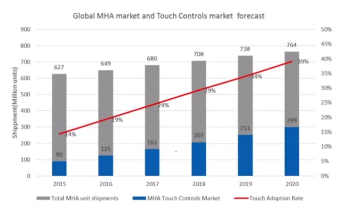
Touch control adoption over the years. Source: IHS Markit.
Why did mechanical controls fall from grace?
But how did a means of HMI that was so strongly favoured by product designers for more than 100 years start to become obsolete? One could argue, that it was the emergence and fast adoption of smartphones that is to blame. Customers got familiar with this means of HMI and started looking for it in other products. So, product designers sought out to satisfy this need by implementing touch controls on their designs.
While this phenomenon surely contributed to the rise of touch controls, there is another major factor that is often overlooked. The thing is, mechanical controls were never perfect. They are cheap and easy to implement, but they also have several drawbacks. Since they feature moving parts, they are prone to wear that eventually will lead to a malfunction. Also, the process of sealing them off is very demanding. Dust and liquid can squeeze in the holes that these controls (inevitably) have, causing further acceleration of the malfunction of the moving parts housed inside of it.
So, we could argue that mechanical controls weren’t the ideal means of HMI that an engineer would use; there simply wasn’t a cost-effective and equally (or more) reliable alternative available.
Indeed, smartphones changed that. The surprising success of the original iPhone in 2007 introduced the world to a whole new means of communication with devices: capacitive touch sensors. Compared to resistive touch sensors (that had been a thing for a while) capacitive touch sensors offer everything a user would ask for: they can work with bare/wet/gloved fingers and they don’t require pens or other gimmicks. Finally, customers started loving touchscreens, and capacitive touch sensors made resistive ones obsolete due to their superiority.

Thanks to gen. 1 iPhone, capacitive touchscreens introduced themselves to the world. Source: Apple
As capacitive sensing dominated the market, a lot of money was spent on R&D and manufacturing. That meant that capacitive touch sensors were finally cost-effective.
Why capacitive touch sensors?
Capacitive touch sensors mitigate the shortcoming of mechanical controls. They have no moving parts at all, thus the risk of failure is significantly less. Ingress protection can easily be achieved too: these sensors can be covered with (virtually) any overlay you want. This makes capacitive sensors ideal for devices where waterproofing or high IP rating is required.
The benefits don’t stop there. Products with capacitive touch sensors offer modern aesthetics, their housing can vary and they are much easier to clean than their mechanical counterparts.
Where’s the catch?
Implementing capacitive touch sensors in a product is, by no means, trivial. Due to the fact that it is a relatively new technology that grew very rapidly, there aren’t many experts and information around it is scarce and hard to find. Arguably, the hardest part of the process is designing a sensor that is compatible with the controller you wish to choose.
To make matters easier, IC makers (the companies that manufacture controllers) release guidelines with design tips to help you ensure the seamless compatibility between the sensor you’ve designed and their chip.
So, hardware engineers follow these guidelines in their designs. The problem with these is that since IC makers want their chips to be compatible with as many designs as possible, they usually are very vague and provide no real guidance. That leaves hardware engineers manufacturing prototypes, and trying to make them work with the controller through an extremely time-consuming process that involves lab measurements, design tweaks, trial and error, and iterations. This process takes, at best, a few weeks and can take up to months.
To make matters worse, this process can by no means guarantee an optimised and verified design. The insights about the underlying physics are very limited, and lab conditions can differ dramatically from certain real-life ones that cannot be recreated in the lab.
A worked example
Let’s say that we want to design a simple remote switch with five buttons, as seen below.

The remote we want to design
How much clearance should we leave between the buttons, so it will be compatible with the controller we want to use?
To answer this question, let’s do the steps we described above. We go through the documentation of the controller we want to use, and find the guideline regarding clearance between buttons:
“Clearance between buttons should be equal to the overlay thickness and range from 0.5 mm to 2 mm”.
You can see how broad this guideline is. Is 0.5 mm better than 2 mm in our case? What if, I expect that this remote will get dropped a lot. So, I plan on adding a 4 mm overlay, to make it more robust. Then, the guidelines do not cover me. One solution would be to follow the common path of hardware engineers, to create prototypes and go to the lab to see what works. However, I will opt for another path.
Simulate your way to optimised products
At Fieldscale, we have created SENSE, the industry’s only simulation software exclusively for capacitive touch sensor simulation. We will use SENSE to solve this dilemma and conclude which is the best design choice for this problem. Here’s the workflow we use:

The workflow with SENSE
Following these steps, we are able to simulate three variations of the design within minutes. We simulated the design with 1 mm, 2 mm and 4 mm clearance. Let’s take a look at the results.

The results from SENSE
As you can easily see, this design guideline severely affects the performance of the sensor. In this case, the design with the 1 mm clearance would limit us to using 1 mm cover glass, while the 4 mm one (which is outside the guidelines but easily simulated) would leave a lot of empty space in the design (places where touch would not register). The design with the 2 mm clearance seems to be the best trade-off for this case.
Should your product feature touch controls?
Going back to the question posed in the title, in our opinion, touch controls are here to stay. The earlier you adopt them, the more successful and well-received your products will be.
However, we discussed the difficulties of implementing capacitive controls and the benefits of simulation. To experience the benefits of simulation yourself, you can request a free trial of SENSE and make your first steps in capacitive sensing today!
Get a free trial now!