onsemi Connected Lighting Platform Provides Head Start for Advanced Solutions
Follow articleHow do you feel about this article? Help us to provide better content for you.
Thank you! Your feedback has been received.
There was a problem submitting your feedback, please try again later.
What do you think of this article?
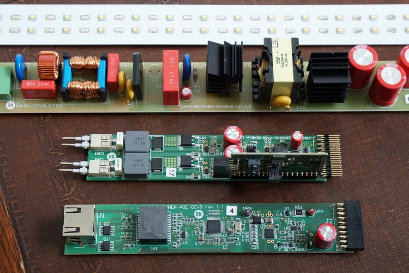
A first look at the LIGHTING-1-GEVK development platform and PoE module.
LED lighting is a hot topic and an area of much innovation, thanks to the constant drive for increased energy-efficiency, together with a growing demand for smart products for use with building automation. The Connected Lighting Platform from onsemi provides a modular kit for evaluation and the prototyping of advanced solutions which integrate high power LED lighting, with software control, Bluetooth Low Energy (BLE), and optional Power-over-Ethernet (PoE).
The key features of the kit are:
- 2 strings × 16 LEDs (7000 Lumen total)
- Dual independent LED channels
- White balance control and 4,000 steps dimming
- Firmware based upon FreeRTOS running on RSL10 Bluetooth 5 SoC
- iOS / Android app for evaluation and development
- AC mains or PoE (802.3bt) power source
- High-efficiency power conversion (>90% at full load)
- Electronic manufacturing friendly and low-cost PCB Layout
- Compatible with DALI Interface via UART Interface
- Debugger port (compatible with JLINK ULTRA Plus)
Platform components
The base kit is provided by onsemi part, LIGHTING-1-GEVK (201-3383) , which includes the LED driver board plus connectivity daughter board, dual LED board, and AC power board.
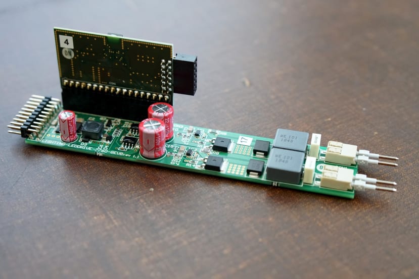
Let’s start by taking a look at the LED driver board.
The LED driver board has a 2x10 connector at one end for connecting to the power supply, with a 2-pin connector at the opposite end for each of the two independent LED channels. A third connector, close to the power supply connector and at the edge of the board, is provided for the connectivity module.
The driver board utilises a pair of FL7760 constant current step−down CCM controller ICs, which are capable of operating with an input range of 8-70VDC and featuring hysteretic LED current control, analogue dimming range down to 5%, and a PWM dimming duty range to 0.2% (at 2KHz). High switching frequency and a source/sink current of 1.5A/2.5A is also specified.
The driver board is designed for an input voltage of 12-60VDC and by default, it will be supplied with 55VDC. The output is specified as constant current 500mA, with dimming down to 0.6% and 12-bit PWM resolution. The module also provides 3.3VDC for the connectivity daughter board.
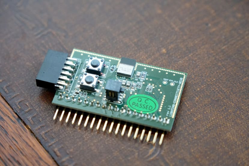
The connectivity board is based upon the onsemi RSL10 ultra-low power 2.4GHz RF System-on-Chip (SoC). This features an Arm Cortex-M3 processor and LPDSP32 DSP core, with support for both Bluetooth Low Energy and proprietary protocol stacks.
The RSL10 boasts a receive sensitivity of -94dBm (BLE mode at 1 Mbps), with a transmit power level of -17 to +6 dBm, and data rates of 62.5 kbps to 2Mbps supported. The device is Bluetooth 5 Certified with LE 2M PHY support. The Cortex-M3 can be clocked at up to 48MHz, with 384 kB of flash memory provided and OTA firmware update supported.
The SoC is available in QFN packaging or as a System-in-Package (SIP) variant which integrates an on-board antenna plus the required passive components. The connectivity module utilises the RSL10 SIP (185-8034) for convenience and adds a Pmod expansion connector, a pair of push buttons, and debugger port for use with a SEGGER J-Link ULTRA+ (131-1321) .
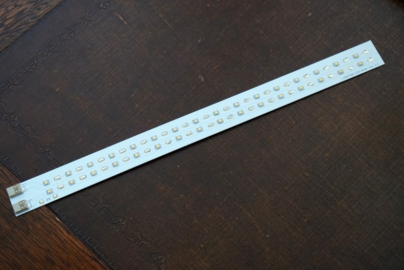
The LED board is fabricated on an aluminium substrate and provides two rows of 16x 3.2V 350mA LEDs, one row populated with cool white and the other warm white variants. The documentation notes that since this may dissipate up to 55W, an appropriate heat sink should be used.
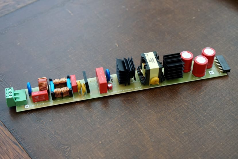
Finally, in the base kit, we have the AC power supply module. This is based upon two onsemi FL7740 PSR flyback controller with PFC. It takes an input of 90-270VAC, with a regulated constant voltage output of 56VDC and max power output of 70W. Efficiency is >92% and power factor is >0.995 (both at 70W output), with a standby power of <170mW.
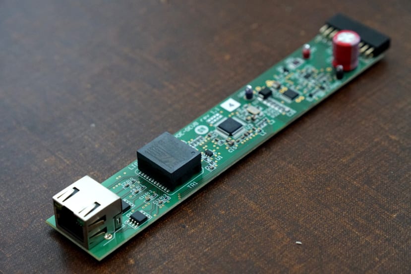
Power-over-Ethernet capability can be added via the onsemi part, LIGHTING-POWER-POE-GEVB (201-3384) . This is based upon the NCP1096 IEEE 802.3bt compliant controller with PHY layer, able to deliver power up to 90W and with MPS circuit to maintain power signature.
Schematics, BOM and Gerbers are provided for the boards, which have been designed with ease of manufacturing and cost-efficiency in mind. They’re also stated to comply with regulations such as layout compliance to EN60950 safety standard for the AC power module, and standby power of less than 200 mW according to CEC2019 standard, for example.
Additional hardware
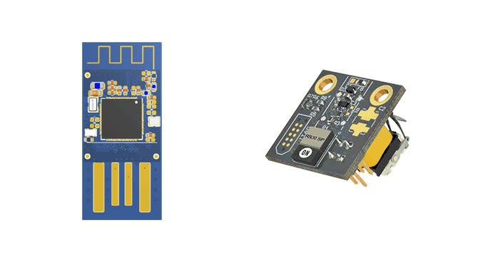
A smartphone app may be used to deliver firmware updates over-the-air, or alternatively, the RSL10 USB Dongle (180-6980) may be used instead with a Windows utility. The provided examples also include support for the BLE-SWITCH001-GEVB, energy harvesting BLE switch (186-1254) .
Getting started
In the next post, we’ll take a look at getting the SDK set up and building the provided examples, before going on to run these and use the accompanying smartphone apps.


Comments