Nixie Tube Clock | Guide to Nixie Tubes | DesignSpark
Follow project
 Dave from DesignSpark
How do you feel about this article? Help us to provide better content for you.
Dave from DesignSpark
Thank you! Your feedback has been received.
Dave from DesignSpark
There was a problem submitting your feedback, please try again later.
Dave from DesignSpark
What do you think of this article?
 I've always had a soft spot for shiny things. So when I discovered Paul Parry at Bad Dog Designs ran a course to make your own Nixie Clock, I couldn't resist ...
Parts list
| Qty | Product | Part number | |
|---|---|---|---|
| 4 | Nixie Tubes | ||
| 2 | 4mm wire ended neon lamp | ||
| 2 | Bespoke Circuit Board | ||
| 1 | Bespoke case | ||
| 4 | 3mm LED | ||
| 1 | PIC Microchip Microcontroller, | 0831309 | |
| 4 | 2.7K resistor | ||
| 4 | 1K resistor | ||
| 4 | EL817 Optocoupler | ||
| 1 | 74141 / K155ID1 Nixie driver | ||
| 6 | 4.7K resistor | ||
| 1 | 78L05 5V voltage regulator | ||
| 2 | 1N5819 Diode | ||
| 1 | 1N4001 Diode | ||
| 1 | UF4004 Diode | ||
| 3 | 390K Resistor | ||
| 2 | 270R Resistor | ||
| 3 | 100nF Ceramic Capacitor | ||
| 1 | 1uF 250V Electrolytic | ||
| 1 | 220uF 16-25V Electrolytic | ||
| 1 | 15pF Ceramic Capacitor | ||
| 1 | 33pF Ceramic | ||
| 1 | 0.22F Capacitor | ||
| 1 | IRFD220 MOSFET | ||
| 3 | MPSA42 NPN Transistor | ||
| 2 | Miniature push button | ||
| 1 | 500mA fuse | ||
| 1 | 32.768KHz watch crystal | ||
| 44 | 1mm sockets | ||
| 2 | 10 way socket | ||
| 2 | 10 way pin header | ||
| 1 | 2.1mm PCB power socket | ||
| 1 | 28 Way IC socket for IC2 | ||
| 1 | 100uH Radial Inductor | ||
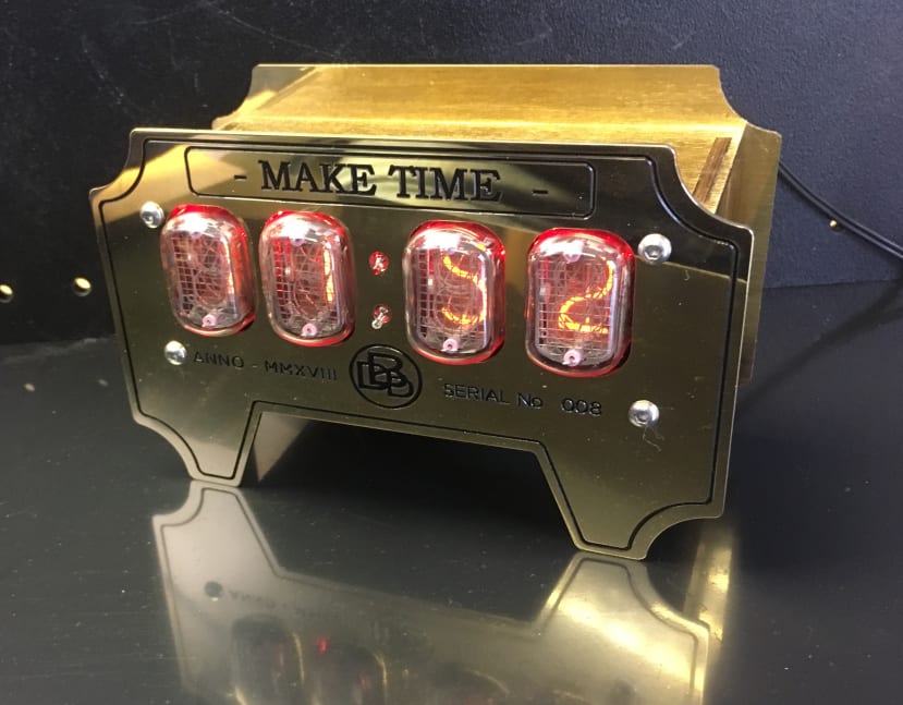
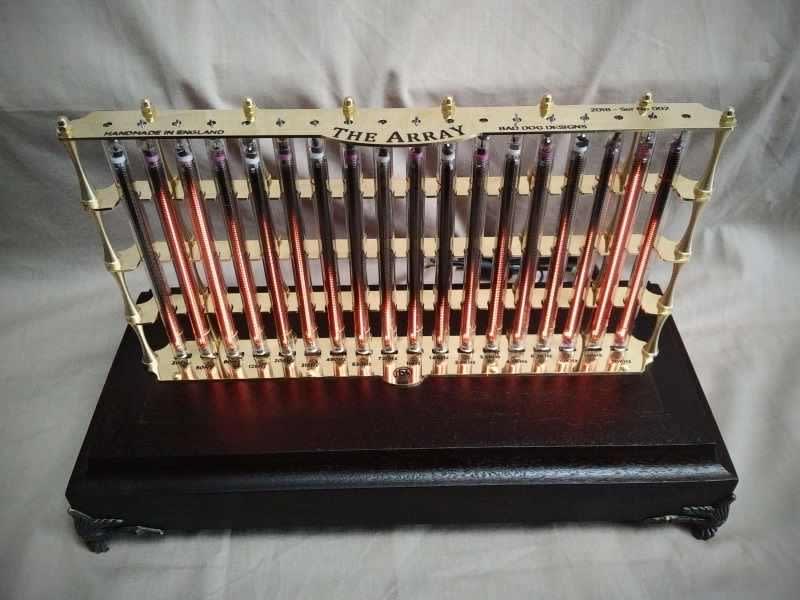
Shiny blinkenlights - and brass. Who can resist a clock like that?
Paul Parry, a member of the Guild of Makers, makes Nixie Tube clocks at his company Bad Dog Designs. He also runs courses where he helps you make your own clock from a kit of parts. Once I knew this there was no way I wouldn't be making one ...
Nixie tubes were used to display illuminated numerals, back in the days before LEDs. They were often used in petrol pumps, scientific equipment, lifts, grocers scales and pinball machines. They are no longer manufactured (although Dalibor Farney does make some by hand.)
![By Hellbus [CC BY-SA 3.0 (https://creativecommons.org/licenses/by-sa/3.0) or GFDL (http://www.gnu.org/copyleft/fdl.html)], from Wikimedia Commons](https://res.cloudinary.com/rs-designspark-live/image/upload/c_limit,w_200/f_auto/v1/project/Nixie2_e17d11670f3227d8b2b544595c31bfda98d38bff)
A GN-4 nixie tube (manufactured by ITT) cycling through its digits.
Image Credit: By Hellbus [CC BY-SA 3.0 (https://creativecommons.org/licenses/by-sa/3.0)]
A Nixie tube is a cold cathode display, used to display numerals using glow discharge. The cathodes are numeral shaped wire.
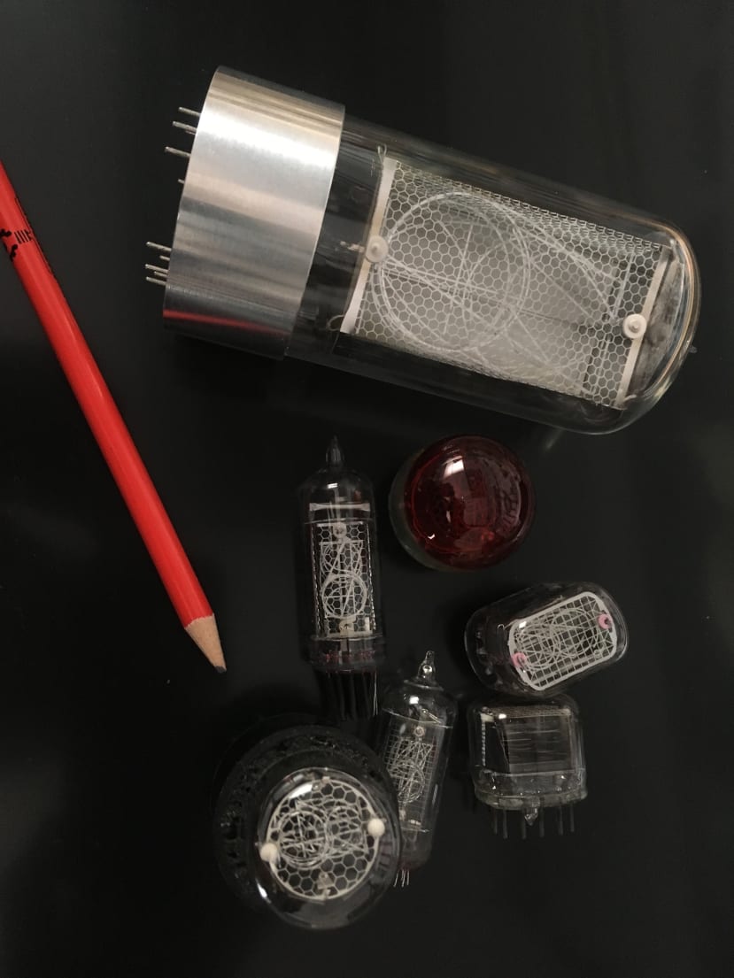
The "cold" bit means it does not rely on thermal energy to make the cathodes glow. Instead, the tube is filled mainly with neon with a bit of mercury (a Penning mixture) at a low pressure. Applying high voltage (170V nominal) to a mesh anode makes an orange plasma or glow discharge surround the cathode.
Side note: If you look at the cathode under a microscope, there is a black space between it and the orange glow - this is known as the Aston Dark Space, and is due to the electrons leaving the cathode with about 1 eV - which is not enough energy to excite the atoms.
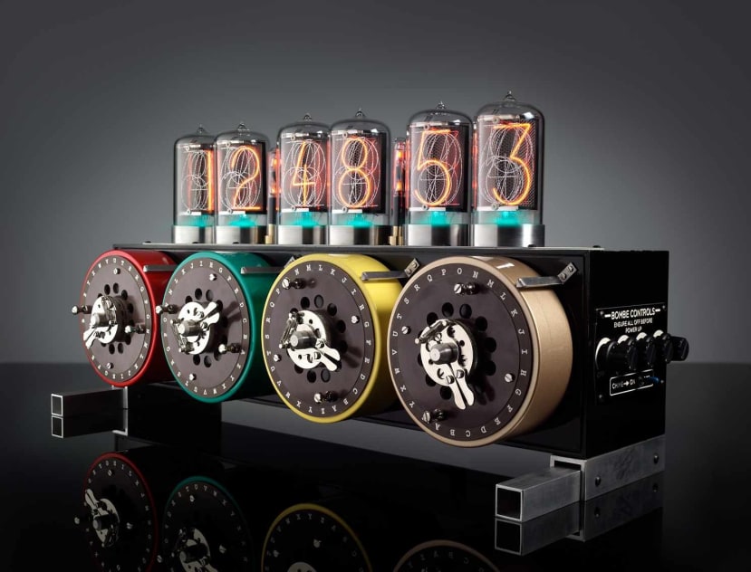

When I arrived at Bad Dog Designs' workshop in Staffordshire, I spent a while drooling at all the shiny things.
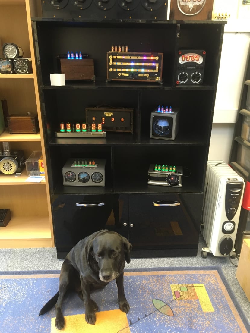
But I soon had my own kit to drool at ...
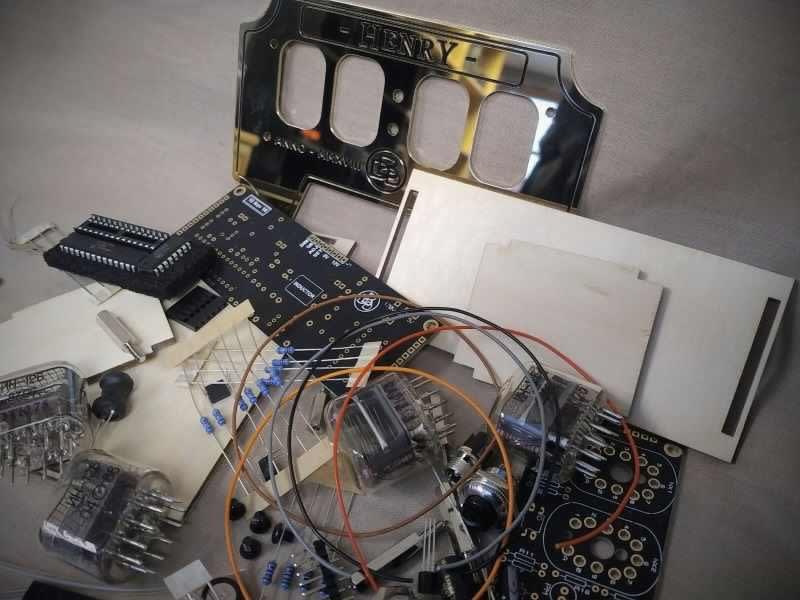
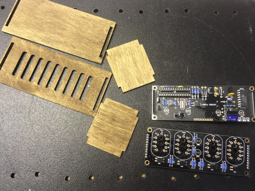
The kit of parts is based on the funk kit from PVElectronics with the case and circuit board being bespoke to Bad Dog Designs. The software was pre-programmed on the PIC.
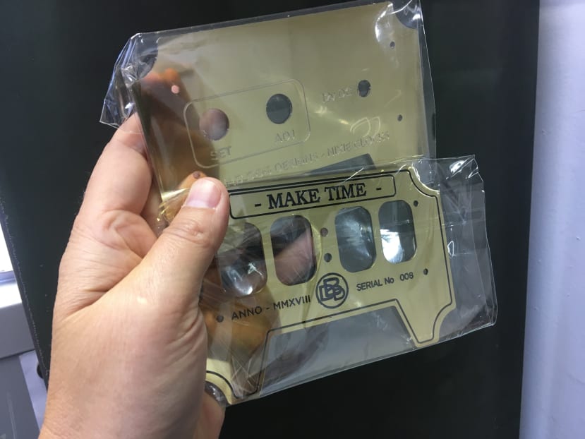
I had ordered my own wording for the front of the case ...
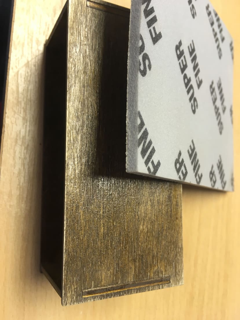
The first step was to sand, dye and build the laser cut wooden case ...
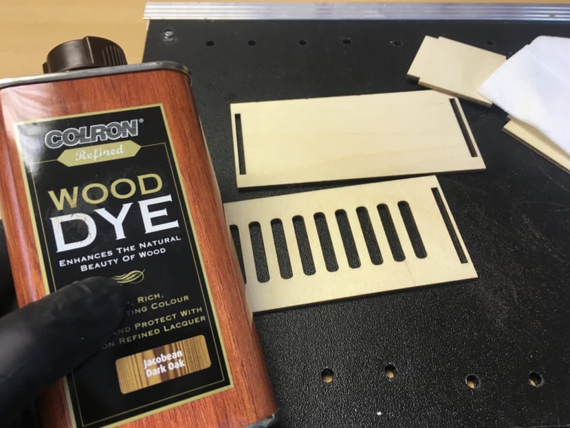
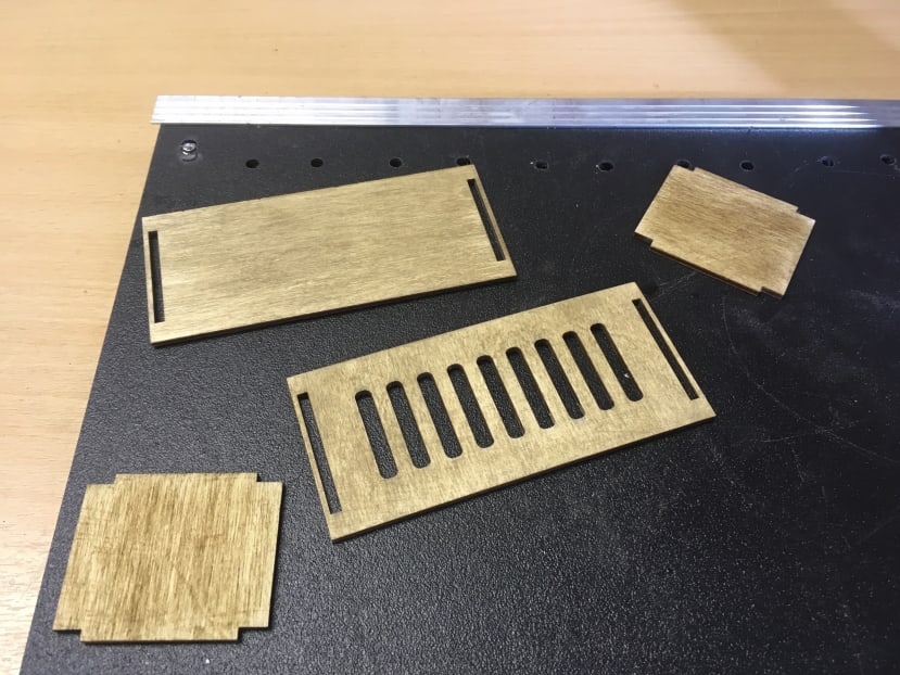
(I forgot to take photos of the assembly and the rubber bands holding it together while the glue dried.)
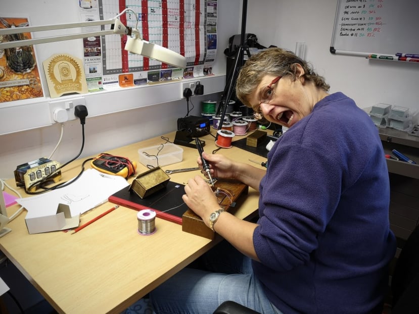
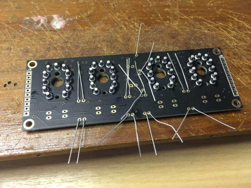
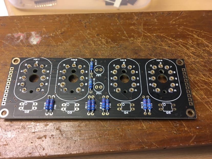
While the dye was drying, I started to assemble the boards ...
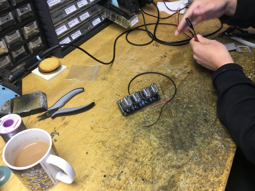
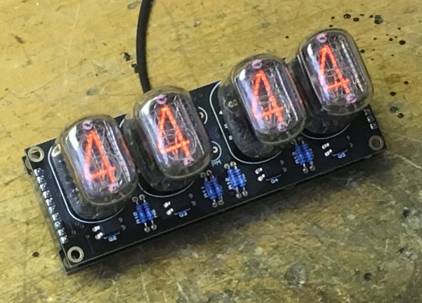
Time to test ...
All the digits work
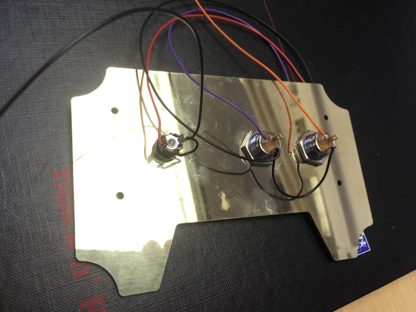
Wiring up the switches:
Final sand and varnish ...
And, ta-dah!

Comments