Linear Induction Motor Project - HYPED (Hyperloop Edinburgh)
Follow article Dave from DesignSpark
How do you feel about this article? Help us to provide better content for you.
Dave from DesignSpark
Thank you! Your feedback has been received.
Dave from DesignSpark
There was a problem submitting your feedback, please try again later.
Dave from DesignSpark
What do you think of this article?
Overview
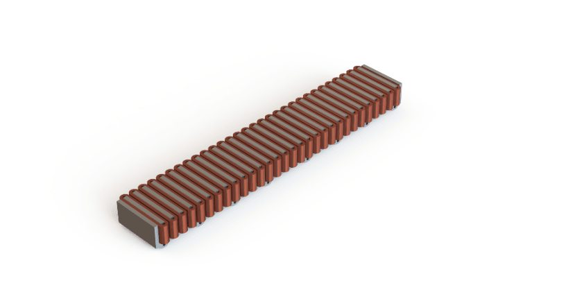
I am part of the Hyperloop Society, more known as HYPED, at the University of Edinburgh and I am the head of the propulsion technical team which means I am responsible for managing everything that makes our Hyperloop pod prototype move forward and levitate. The particular project I will be writing about in this article is the Linear Induction Motor (LIM) which creates the linear thrust that drives our pod forward.
This year we are delighted to be the recipients of this year’s RS Grassroots Student project fund and we will be using this to aid with the manufacture of our LIM!
Objective(s)
The main objective of our project is to win the traction award at this year's European Hyperloop Week (EHW) however this objective is an ambitious one. I tend to find that big goals are most often achieved when there is incremental focus on differing goals which work towards the main one. Our short-term objectives are as follows:
- Successfully wind 30 copper coils within tolerance
- Pot these coils in a thermally conductive and electrically insulating potting fluid
- Mount the coils on the motor and connect the coils without introducing any shorts
- Produce a working motor that produces thrust in line with our simulation results
Methodology
The design methodology mainly consists of iterative simulations where key parameters such as the number of turns per coil, number of coils, tooth width and height are changed to achieve a close to, but not fully saturated motor core. In these conditions, optimal thrust and efficiency are achieved.
As we are a student-led society, we have to ensure that we work in conjunction with our individual university timetables which makes coordinating large project work like our pod very difficult. To manage this, we have several weekly meetings where we take the time to put in extra work and collaborate amongst other teams.
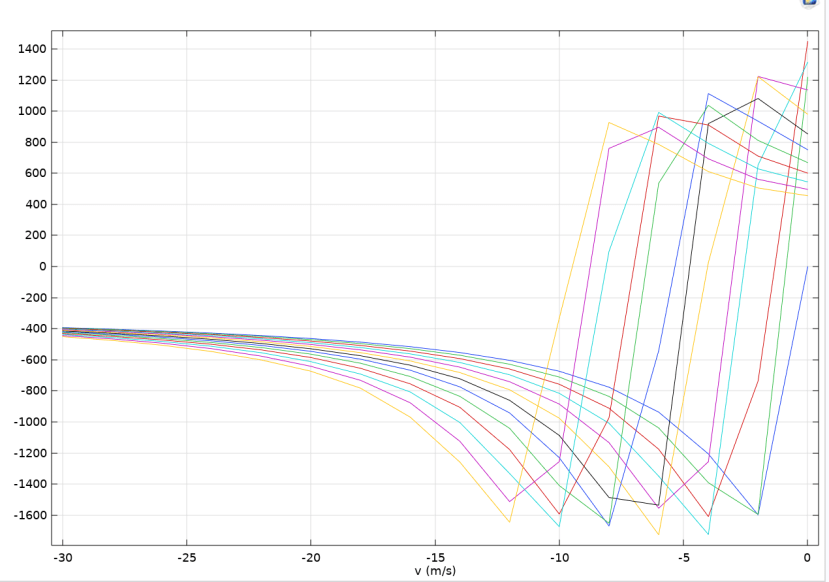
Once a design has been decided on, COMSOL simulations are run to obtain thrust versus velocity characteristics which are then the values that our motor controller bases its response on so that maximum available thrust is achieved at all operating velocities of the pod.
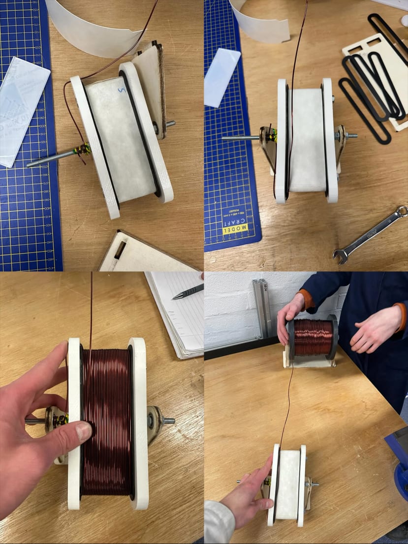
What remains for the LIM is the manufacturing which is a very large task in itself. Luckily, this year, we have managed to obtain a sponsorship from a local laser-cutting company by the name of Tannlin and they will be manufacturing the motor core for us. However, we still do a vast amount of manufacturing in-house and all of our copper coils are wound by hand.
We have designed a jig that makes this process less prone to human error and we have also designed a winding bobbin that ensures that the copper coils are electrically insulated from the motor core during operation. Obviously, the copper wire that we use is enamelled, however, this coating can easily be scratched when either mounting the coils onto the core or during the winding process itself. This is where the project fund comes in. The materials for the winding bobbins will be sourced from RS and this includes but is not limited to Nomex Paper and Kapton tape. The Nomex paper will sit in between the coils and the motor core to ensure a physical barrier preventing shorts between them.
The bobbin is made by cutting the nomex paper into a net shape which is then wrapped around a model of the motor core tooth. Then, a top and a bottom part of the bobbin is stuck to the nomex paper and the assembly is then mounted onto our winding jig so that the coils can be wound.
Once wound, the bobbin is taken off the rig and the tooth model is removed and replaced with a wax model tooth. This new assembly is then placed inside a 3D-printed potting mold and the potting fluid is poured into the mold ensuring that once removed, the coils are fully insulated and have optimal thermal dissipation to prevent overheating. The coils are then mounted on the motor core and the 3-phases are soldered together and covered in Kapton tape to keep them insulated.
Next Steps
The next step for us is to wind these 30 coils which is a lengthy process. Luckily the method we have developed is relatively quick and the rough time per coil will be 40 minutes and with 3 winding jigs working simultaneously, we will be able to finish the coil winding in around 7 hours. Once the winding has been done, we will be potting them as explained in the methodology however the coils must be wound within our tight tolerances to ensure they fit inside the potting molds.
Get in Touch
If you would like to hear more about our student-led society you can find out more at HYPED – Hyperloop Edinburgh (hyp-ed.com), on Instagram @hypededinburgh or email us at team@hyp-ed.com.