Introducing the Raspberry Pi B+
Follow articleHow do you feel about this article? Help us to provide better content for you.
Thank you! Your feedback has been received.
There was a problem submitting your feedback, please try again later.
What do you think of this article?
If you enjoy interfacing your Raspberry Pi with the real world by (for example) connecting sensors or controlling LEDs and motors, there will have been times when you have wanted to have more inputs and outputs on the GPIO header, or a couple more USB ports for connecting peripherals. Well, the good news is that the folks at the Raspberry Pi Foundation have obviously listened to the growing community of Raspberry Pi users and developed an enhanced version of the Raspberry Pi called the model B+ (811-1284)
Raspberry Pi B+ First Impressions
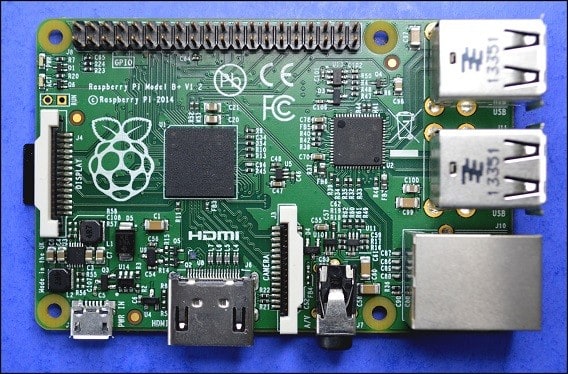
On first sight the new Raspberry Pi model B+ (811-1284) looks quite different to previous models and indeed nearly all of the new features and enhancements introduced on the model B+ relate to connectivity and physical (as opposed to electronic) design.
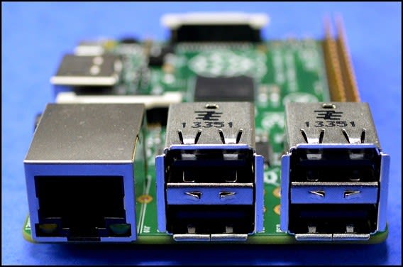
Two more USB ports have been provided which in many applications negate the need for an external USB hub. I often want to connect a keyboard, mouse and WiFi adapter to my Raspberry Pi, and on the new Raspberry Pi B+ module I can do so without requiring a USB hub and still have one USB port free.
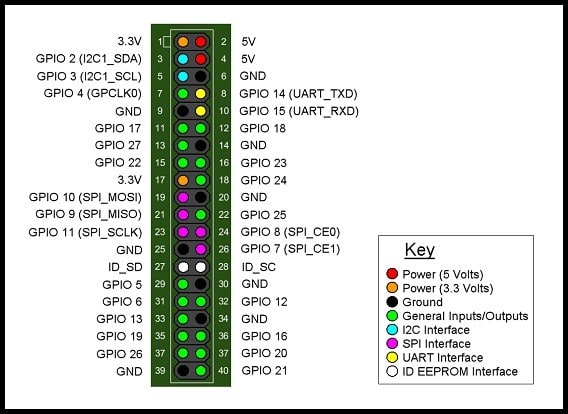
There are now a total of 40 GPIO pins, 26 of which can be used as digital inputs or outputs. Perhaps more importantly, 9 of the 14 new GPIO pins are dedicated inputs/outputs (pins which do not have an alternative function), so now if you want to use the onboard UART, I2C or SPI bus you can do so and still have plenty of free GPIO inputs and outputs to play with. The new expanded GPIO pinout is as shown below.
Pins 3 and 5 (GPIO 2 and GPIO 3) both have on board 1.8KOhm pull-up resistors fitted to them (and they also double up as the I2C interface pins). Pins 27 and 28 (ID_SD and ID_SC) are reserved exclusively for ID EEPROM use and can not be used as input/output pins. The layout of the GPIO pins is backwards compatible with previous Raspberry Pi models – pins 1 to 26 are directly compatible with previous Raspberry Pi GPIO headers, although it should be noted that the whole GPIO header has been moved away from the corner of the board to allow room for an additional mounting hole - therefore any plug in board designed for previous Raspberry Pi models may be compatible, but will not sit directly above the Raspberry Pi B+ board because the GPIO header has been repositioned.
As far as other onboard connectors are concerned, the 3.5mm audio jack output socket and RCA composite video output socket (as found on previous Raspberry Pi models) have been replaced with a single 3.5mm 4-Pole A/V socket located next to the HDMI socket (which itself has been moved slightly on the PCB) and the power connector on the new Raspberry Pi model B+ has been relocated next to the HDMI socket. This means that all audio video and power connectors are now located along one side of the PCB which will help keep all connected cables tidy.
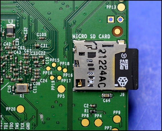
Amongst other changes introduced on the new Raspberry Pi model B+ (811-1284) , the SD memory card slot used on previous Raspberry Pi models has been replaced with a Micro SD memory card slot, the status LEDs have been moved to the opposite end of the PCB and now consist only of a red “PWR” LED and a green “ACT” LED, and the PCB now has 4 mounting holes laid out in a rectangular pattern, which will make mounting the PCB securely so much easier.
However, please note the new Raspberry Pi model B+ uses the same CPU and GPU architecture as the model B and has the same 512MB of onboard SDRAM, so I’m afraid if you are expecting enhanced performance or computing power you may be disappointed. The only significant change in the onboard electronics is that linear power circuitry used on previous Raspberry Pi boards has been replaced with a more efficient (and significantly “beefed up”) switch mode design.
Time to give the new Raspberry Pi model B+ (811-1284) a little bit of a workout…..
I really like 7 segment LED displays, because of their simplicity and their “retro” look, so I decided to use the expanded GPIO port to directly control a number of seven segment LED displays, without the need for additional driver IC (or having to multiplex individual elements or characters). Rather confusingly perhaps, each “seven segment” LED display actually has 8 terminals plus a common terminal. Seven of the terminals control the seven segments of the display and the eighth is connected to the decimal point. I used common cathode seven segment displays (RS part number 588-639) so that I could connect the Raspberry Pi’s GPIO pins directly to the input terminals and connect the common cathode terminal of each display to ground via a single 47 Ohm current limiting resistor. The pinout of the seven segment displays I used is shown below.
Each pin is connected to the segment of the display as indicated by the letter next to the pin, so for example, pin 1 is connected to segment “e”. Pins 3 and 8 are the common cathode pins and either one may be used. I wanted to use the seven segment displays to display some useful information, so I thought it would be fun to connect a 1 wire temperature sensor (DS18B20, RS part number (540-2805) to the Raspberry Pi model B+ to measure the ambient temperature.
Building the Circuit
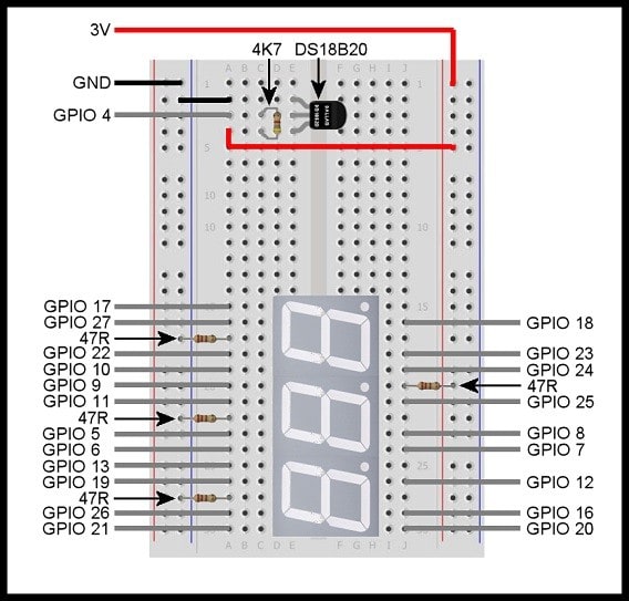
The DS18B20 1-wire temperature sensor will (by default) use GPIO 4 as an input. I decided not to use GPIO 2 or GPIO 3, because of the pull-up resistors connected to them, and also decided not to use GPIO 14 and GPIO 15 because they double up as the UART interface (which is enabled by default), and it’s often useful to connect to the Raspberry Pi in console mode using the serial interface. This left me with 21 available GPIO pins – just enough to connect three seven segment LED display modules (ignoring the decimal point “segments”). The finished circuit is shown below as built on a small breadboard, with all connections to the new Raspberry Pi model B+ GPIO pins as indicated.
The three 47 Ohm resistors on the left hand side are the current limiting resistors for each seven segment LED display, and the 47 Ohm resistor on the right hand side causes the decimal point on the middle seven segment LED display to be permanently illuminated. The DS18B20 1-wire temperature sensor is shown at the top of the breadboard and only requires one 4.7K Ohm resistor to function properly.
Setting up the Raspberry Pi
To enable kernel support for the DS18B20 1-wire temperature sensor, open the file “/etc/modules” and add the following two lines to the end of the file:
w1-gpio
w1-therm
There are various ways you can do this but the simplest is to enter the following command at the command line prompt:
sudo nano /etc/modules
This will open the file in nano where you can add the extra lines and then save the file and exit by pressing Ctrl+X, Y and finally Enter
You will need to reboot your Raspberry Pi model B+ for the changes to take effect. You can do this by entering the following command at the command line prompt:
sudo reboot
When your Raspberry Pi model B+ has rebooted, log in and the then enter the following command at the command line prompt:
cd /sys/bus/w1/devices
Now enter “ls” at the command line prompt. You should see something similar to the following:
28-000004d0963d w1_bus_master1
Make a note of the long string of numbers and letters – this is the serial number of your DS18B20 temperature sensor and you will need it retrieve data from the sensor (your serial number will be different to the one shown above).
Writing the Software
I have written a Python3 program to take a temperature measurement (in deg C) every second and display the measured temperature in the format “##.#” on the three seven segment LED modules connected to the GPIO header on the new Raspberry Pi model B+. The program is designed to display the measured temperature as long as it is in the range -9.9 deg C to 99.9 deg C. Outside this range the LED display will show “EEE”.
A full listing of the program can be downloaded from GitHub by going to https://github.com/mi0iou/RPi_Thermometer
Putting it all Together
Run the program from the command line prompt by entering the following (where “xx-xxxxxxxxxxxx” is the serial number of your DS18B20 temperature sensor):
sudo python3 rpi_thermometer.py xx-xxxxxxxxxxxx
After a short delay, the temperature will be displayed on the LED display modules. Press Ctrl+C to terminate the program.
The whole setup can be made a lot more portable (as shown in the photo below) by connecting a WiFi adapter to the Raspberry Pi model B+ and then connecting using SSH from another computer to access the Raspberry Pi and run the software.
Conclusion
The new Raspberry Pi model B+ is every bit as easy to use as it’s predecessors, and the addition of extra GPIO pins and onboard USB ports will certainly open up new possibilities for experimenters and hackers. The new design and layout of connectors is a logical progression from previous models and I believe will make the new Raspberry Pi model B+ even more adaptable and easy to incorporate into a wide variety of projects.
I’m sure there will be a few who bemoan the fact this new model does not have a faster processor, or more RAM, but I think the current architecture is still more than adequate, and using the same basic architecture as previous models maintains backwards compatibility, which is important. I don’t doubt that in the long run the new Raspberry Pi model B+ will become the dominant model, but it will not immediately make previous models obsolete.
The great strength of the Raspberry Pi has always been its ease of use (compared to a microcontroller) combined with the ease with which the GPIO interface can be programmed and used to connect with the real world. The new Raspberry Pi model B+ is a logical and welcome addition to the Raspberry Pi family, and one which will have an even wider appeal to hobbyists, educationalists and professionals alike.
Order your Raspberry Pi Model B+ (811-1284)
More about Raspberry Pi on DesignSpark
My Website: www.asliceofraspberrypi.blogspot.co.uk
Twitter: @TomHerbison

