Interfacing a 1967 Paper Tape Reader: Part 1
Follow article
 Dave from DesignSpark
How do you feel about this article? Help us to provide better content for you.
Dave from DesignSpark
Thank you! Your feedback has been received.
Dave from DesignSpark
There was a problem submitting your feedback, please try again later.
Dave from DesignSpark
What do you think of this article?
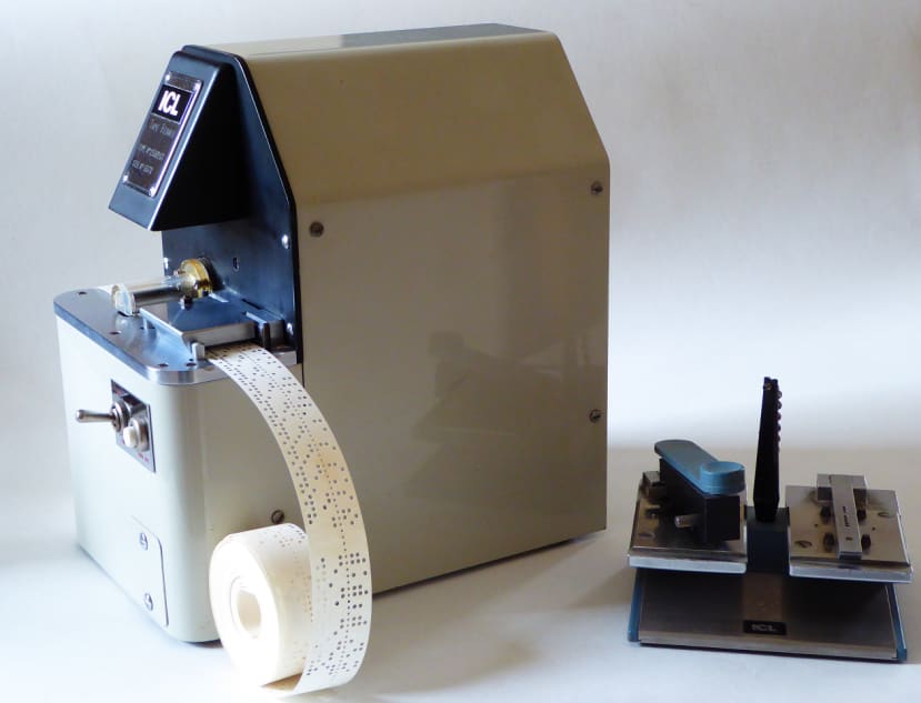
Computer engineering 1960s style. Before floppy disks, punched paper tape was used for program and data storage on most ‘desk’ computers up until the late 1970s. This machine is a tape reader, specifically a 250 character/sec TRM250 from Elliott Automation. The gadget on the right is a hand punch for ‘manual’ tape editing.
Project Aims
OK, so what’s the point of interfacing a piece of 55-year-old storage technology to a modern computer system? Well….
- Because it’s there: indeed it is, sat on a shelf for the last thirty years gathering dust. I’ve never seen it work and that bugs me.
- Nostalgia: I’ve used one of these things for real while working as a student engineer in the 1970s and want to relive the whole punched paper tape ‘experience’. I’ll go into what that is later on.
- Design to last: More seriously, in those days the phrase ‘built-in obsolescence’ had no place in the lexicon of engineering terms. Nowadays, our throw-away society and its impact on dwindling global resources is looking decidedly ‘unsustainable’. Admittedly, old computer equipment seems to have been designed for a 100-year lifetime of brutal misuse, and that turned out to be excessive. Read on to see an example of how they did it.
- Repairability: In order to provide a lifetime somewhat longer than a year, any equipment containing moving parts must be designed for service and repair. That doesn’t just mean spare-part availability, it includes features to aid fault location and easy access to case internals – screwed not glued.
Paper Tape Storage
Punched paper tape had been used to control looms in the 18th century. The first commercial computers of the 1950s were able to use magnetic tape for mass storage, but mag tape units were very expensive and complex to drive. For the small desk-size machines such as the Elliott 903, paper tape offered a much cheaper and simpler alternative. This 18-bit computer only possessed up to 16 kwords of working memory or RAM and could only run one program at a time. There was no room for what we would call an Operating System (OS) controlling a mass storage device such as a mag tape unit. Paper tape was ideal for small systems like the 903 before the invention of high-capacity semiconductor RAM and the floppy disk drive.
The Technology
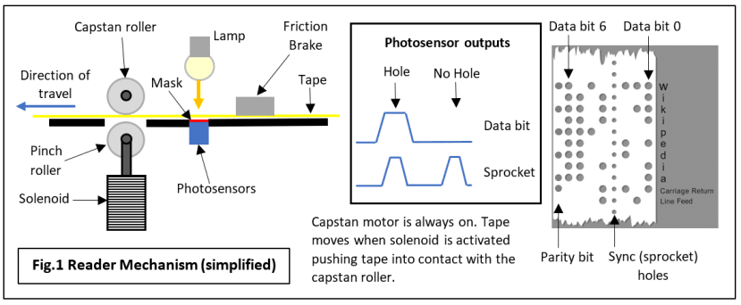
The basic principle of punched paper tape storage of digital data is hardly sophisticated: a strip of paper is punched with holes representing a logic 1 on a 0.1 in. pitch grid pattern (Fig.1). No hole represents a logic 0. Early teleprinter communication systems based on Baudot code used a narrow tape, 11/16 in. wide able to accommodate a 5-bit code character plus a sprocket or sync hole across its width. Later, the width of ‘standard’ paper tape was increased to 1 in. enabling up to 8-bit codes to be used.
In order to read the tape, all you need is a row of hole sensors across the tape path with the smaller sync hole being used to indicate when a data character is properly lined up. It is possible to build a working reader based on a row of spring-metal strips that drop through the holes making electrical contact with a metal plate on the other side of the tape. In theory, the tape can be pulled through by hand because the sync channel ensures the data channels are ‘sampled’ at the right time. In practice, some sort of motorised tape transport is more convenient, especially when a big program or data file is to be loaded into computer memory.
Overcoming inertia
The inertia of the spring contacts rapidly becomes a big problem when the tape is pulled through at much more than 10 characters/sec - the contact doesn't have enough time to drop through a hole and make an electrical connection before the tape moves on. The solution was to use a strong light source combined with a set of electronic photosensors instead. Hence the hole-sensing system ceased to be a limitation on reading speed. Unfortunately, the early motorised tape transport systems then became the blocking factor for speeds much above 100 characters/sec. Those readers used an electric motor driving a sprocket wheel whose teeth engaged with the sync holes in the tape. The trouble was once again our old friend inertia, this time in the form of the tape’s resistance to move as the sprocket began to turn. After only a few starts, the sprocket holes in the paper became oval, ruining the alignment accuracy and leading to read errors. In extreme cases the sprocket acted like a circular saw resulting in no tape movement at all. Paper tape reader transport mechanisms required a major rethink.
The Elliott TRM 250 tape transport
The subject of this project, a 1967 Elliott TRM 250 paper tape reader features photoelectric sensing and a transport system that enables reading speeds of up to 250 characters/sec. Fig.1 illustrates the basic principles of its operation. Before describing how it works, I must mention one other essential requirement of a paper tape reader, apart from reading the data accurately. It must be able to Stop-on-Character: when a particular character appears over the sensors, say 0Dh, the ASCII code for Return, the tape transport can be stopped immediately. That was easy with a stepper motor driving a sprocket at relatively low speed, but it gets a lot more tricky at high speeds. This is how the TRM 250 does it:
- The capstan motor runs continuously at a constant speed. The tape does touch the rotating roller but remains stationary because a spring-loaded plate acting upon it behaves as a friction brake.
- To start the tape moving past the sensors, a solenoid is energised which causes a pinch roller to force the tape against the rotating capstan. The tape is thus pulled through overcoming the carefully adjusted force of the friction brake.
- To stop tape movement, the solenoid is de-energised, the pinch roller drops and the drive ceases. The friction brake ensures the tape moves no further by killing its momentum and thus guarantees ‘stop-on-character’.
The continuously-running drive motor provides for near-instantaneous acceleration of the tape when the next character is requested because there’s no time wasted as the motor gets up to speed.
Inside the Machine
Let’s take a look at the reader with the covers off.
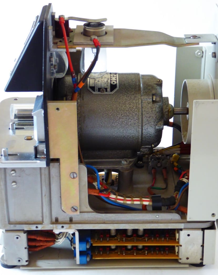
Side view with main cover removed. Notice the cast alloy chassis and the thick steel supports – all fixed together with machine screws in tapped holes or captive nuts. Note the mains synchronous fractional-horsepower motor directly driving the capstan. It runs without any control circuits at a constant speed set by the mains frequency. It’s quiet too. The motor also drives a cooling fan at the back, not to cool itself or the electronics: just to remove heat from the 48W car headlamp bulb used to illuminate the sensors. The 12-volt bulb was actually under-run, being driven from a 9.5 Vac supply which significantly increased its life. I’ve located an LED drop-in replacement that takes rather less than the 3.5A of the old filament lamp. The two PCBs on the bottom contain the photosensor amplifier circuits based on discrete transistors.
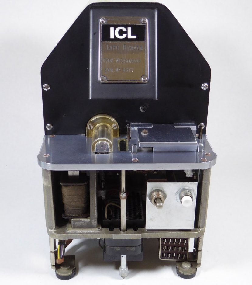
Front view with front cover removed. Inside the hood with the ICL nameplate is a carefully shaped Perspex collimator that focuses the lamp light into an even line along the line of photosensors. The capstan roller with its finger guard sits above a thick alloy deck. Next to it is the sensor array covered by a mask with a ‘diablo’ or cotton-reel-shaped hole above each photosensor. The shape of these holes ensures a constant light level as a round hole in the tape passes across the collimated beam. To the right of the sensor array is the hinged flap with friction brake attached. The four posts around the friction brake are tape guides; the front two are adjustable to suit different tape widths. Under the deck on the left is the pinch roller solenoid with the pinch roller itself just visible under the capstan. On the right at the bottom is a test connector which can be accessed via a small ‘hatch’ held in the front cover by two quick-release screws. The connector pins are actually loops for the easy attachment of a standard ‘scope probe. They allow the amplifier outputs and other signals to be checked out quickly.

View of underside with covers removed. The massive alloy chassis is very obvious from this viewpoint. The two identical 5-channel amplifier boards are easily extracted once the bottom cover is removed because the latter forms part of the rear cover (see next picture).

Rear view with bottom cover removed. This picture reveals another example of designing for maintenance: the PCBs can be pulled out of their edge connectors for repair or replacement. That’s not all. The multi-turn potentiometers (the white objects) which set the gain for each amplifier are fully accessible with the PCBs in situ. Also visible are the two Plessey multipin connectors. The one on the right handles the amplifier outputs and power rails. The left-hand connector has the mains power input for the motor and the low-voltage lamp power. Various switch and pushbutton signals are also found here.
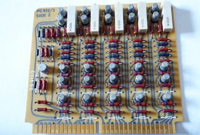
An amplifier PCB. Note the neat layout with the gain adjustment pots lined up along one edge. The transistors are all identical which cut down on the variety of spares that needed to be stocked. This type is now obsolete and unobtainable, but it should be possible to find a modern equivalent if some have aged badly.
Finally
Is there any point in resurrecting old technology like this? Probably not. But I’ll try anyway just for the fun of remembering the days when computers were so noisy and tactile. Interacting with a computer via a teletype machine was so much more of a physical experience: the keyboard had real ‘force-feedback’ as a pressed key kicked back before the typed character was echoed to the printer accompanied by a lot of whirring and crashing sounds. The machine felt alive as its drive motor was permanently running too. If anybody out there has an unwanted ASR33 teletype, I’d love to hear from them!
BTW this machine does not represent the final state-of-the-art. In 1976 I also used the dual-capstan bi-directional GNT 4101 which could shoot the tape across the room at a blistering 2000 characters/sec. That’s 5 metres/sec. The Ferrari of paper tape readers.
Coming up in Part 2
I’ve already powered up the motor and lamp, finding them to be in working order. The next step is to connect a dual-rail power supply to the amplifier boards, and with the lamp switched on, check out each bit-channel via the front test socket. If they work, then I can design and build an interface to provide TTL-level outputs. After that, a solenoid driver circuit will be constructed based on a suggested design in the technical manual – luckily all the transistor types are still available!
If you're stuck for something to do, follow my posts on Twitter. I link to interesting articles on new electronics and related technologies, retweeting posts I spot about robots, space exploration and other issues.
Comments