How can I add dimension lines in DesignSpark PCB?
Follow tutorial
 Dave from DesignSpark
How do you feel about this tutorial? Help us to provide better content for you.
Dave from DesignSpark
Thank you! Your feedback has been received.
Dave from DesignSpark
There was a problem submitting your feedback, please try again later.
Dave from DesignSpark
What do you think of this tutorial?
This tutorial requires:
DesignSpark PCB V11.0.0Dimension lines are used on the PCB. Here we have created a PCB-only component accessible from "Add Component". All the lines drawn are on the documentation layer.
When a dimension line is required simply add it to your PCB as you would any other component, then move, rotate and align to the correct position. Two components are provided which makes adding them to your PCB simple. If you need, simply extend the line using the 'open shape' with the line set to the required width.
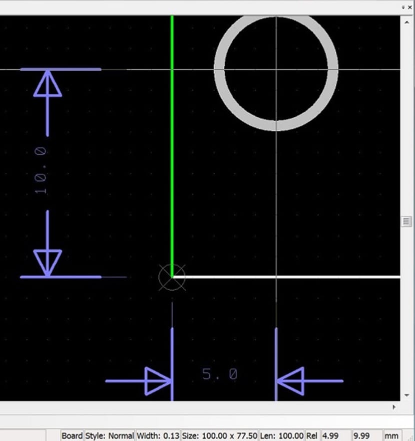
Figure 1. Shows the dimensions lines placed to show the location of the hole from the board corner.
Set the relative origin at the desired reference point and use the cross-hair cursor (Shift+C shortcut toggles through options) to allow easy placement and alignment.
The cursor position is displayed at the bottom of the screen which helps placement or use the shortcut “=” to enter the relative position of the arrow point.
Additional reading
The attached zip file contains some basic arrows. Add them as new file under Library Manager > Components to use it in your schematics. More on the Library Manager here: https://www.rs-online.com/designspark/how-can-i-use-the-library-manager