Homemade Ambilight | Ambilighting Guide for PC | DesignSpark
Follow project
 Dave from DesignSpark
How do you feel about this article? Help us to provide better content for you.
Dave from DesignSpark
Thank you! Your feedback has been received.
Dave from DesignSpark
There was a problem submitting your feedback, please try again later.
Dave from DesignSpark
What do you think of this article?
 The objective of this project is the imitation of the Ambilight function developed by Philips TVs. This function synchronizes the rear LEDs of the TV with the image emitted by it.
Parts list
| Qty | Product | Part number | |
|---|---|---|---|
| 1 | RASPBERRY PI 3 MODEL B SBC | 182-6547 | |
| 2 | RS PRO HDMI to HDMI Cable, Male to Male - 1.2m | 876-2393 | |
| 1 | RS PRO Male USB A to Male Micro USB B USB Cable, 1.2m, USB 2.0 | 876-2403 | |
| 1 | Transcend 16GB microSDHC U1 | 124-9640 | |
| 1 | HDMI Splitter | ||
| 1 | Video capture | ||
| 1 | LED strip | ||
| 1 | Power supply 5V | ||
Software:
Firstly, we will begin installing the Raspbian OS onto the Raspberry Pi by loading the ISO image of Raspbian onto an SD card using the Balena etcher programme.

Secondly, we will install the SD card into the Raspberry Pi and start the OS on it. After correctly booting the Raspbian, we can configure it from configure/interface. We need to active SSH and install Hyperion from the terminal using these commands:
Downloading: wget https://github.com/hyperion-project/hyperion
Installation: sudo dpkg -i Hyperion-2.0.0-alpha.8-Linux-armv7l.deb
When the installation is finished, we will see this message on the Terminal:
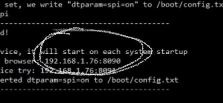
Then we will need to search for the IP of the image (including :8090) in the browser of the other device and it will direct us to the Hyperion's settings.

We can then configure everything, depending on the number of LEDs we place on the TV.
Hardware:
The first step will be to place the LED strips around the back part of the TV (as illustrated in the last image) so that the same number of LEDs are both on the horizontal and vertical axis. This means that whether we place 22 led on the right side and 35 above, we will have to place 22 on the left side and 35 below.
After we have finished placing the LEDs around the screen, we will cut the end of the cable and we will see that there are both red and black cables inside. These cables must be connected to the cables of the respective colour of the LEDs. Now we will connect the end of the USB cable that we have not used yet to the power supply and the other micro SD cable (not modified) to the Raspberry Pi. In my case, the power supply has three USB ports, so no modification is required by me.
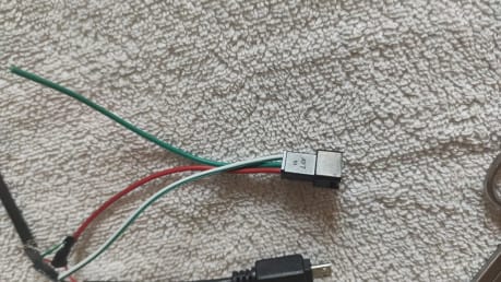
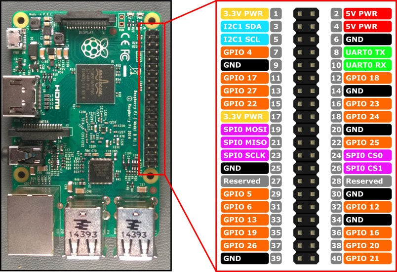
Next, we will connect the green cable of the LEDs to the Raspberry’s 12 pin.
Finally, we will connect the HDMI of the imaging device that interests us: PC, TV, Game Console... to
our splitter and other HDMI to the Raspberry (using the captor) and other to our TV.

Comments