Hands-on with the INMOS Transputer Part 1: Introduction
Follow article
 Dave from DesignSpark
How do you feel about this article? Help us to provide better content for you.
Dave from DesignSpark
Thank you! Your feedback has been received.
Dave from DesignSpark
There was a problem submitting your feedback, please try again later.
Dave from DesignSpark
What do you think of this article?
Selecting a transputer platform and exploring its basic features.
In a previous article, we took a fresh look the INMOS transputer, a pioneering microprocessor which in the 1980s looked set to revolutionise computing with its inherently scalable architecture. In this article, we now take a look at some of the available transputer development options, before settling on an INMOS evaluation board to use for gaining some hands-on experience.
Picking a platform
Luckily, as a long time fan of the platform there are a number of transputer systems in the collection which might be used for experimentation and gaining hands-on experience.
So let’s start by taking a look at some potential candidates.
IMS B017
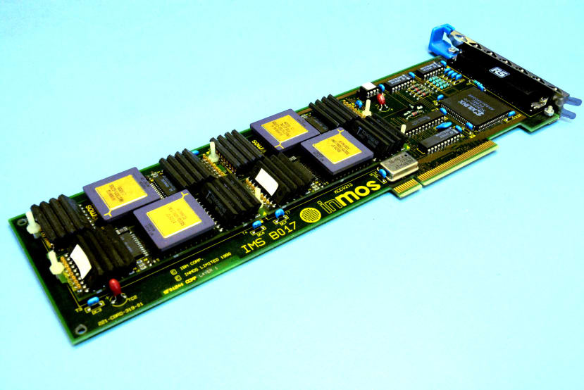
An IMS B017 Micro Channel Architecture (MCA) bus card for use with an IBM PS/2 system can be seen above. This features four TRAnsputer Module (TRAM) slots and a transputer link bus adapter, plus a 37-way D-type connector with link and reset etc. signals.
Most TRAMs occupy a single slot and provide a single transputer plus external memory, although there are also larger TRAMs and those which provide I/O such as graphics and SCSI. The board pictured above is fitted with four IMS-B411 TRAMs, each with a T805-G20S transputer and 1 Mbyte DRAM. However, while we do have a suitable IBM PS/2 into which we could install the B017 card, we haven’t as yet managed to track down the PS/2 device driver software, IMS217.
While it may be possible to get the B017 card working without the IMS217 package, this feels like it could easily be something of a challenge and a task for another day.
Parsytec X’plorer
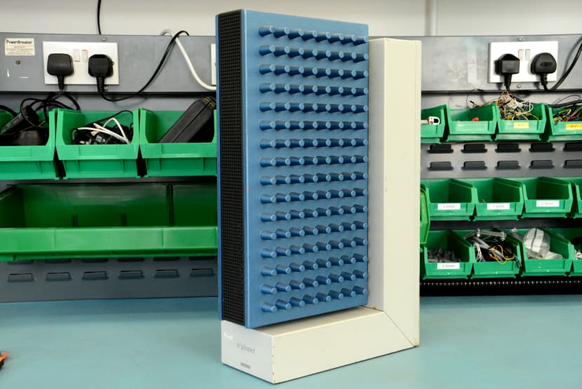
The Parsytec X’plorer is arguably one of the most beautiful — or at the very least you would have to concede most unusual looking — desktop computers ever built. Housed in a tower configuration with two great big blue cast aluminium panels, the computer won an iF Design Award in 1994. However, while you’d be forgiven for thinking that those blue panels were heatsinks, the PCBs within are not thermally coupled to them and instead fans at the rear blow air through the chassis.
The X’plorer was designed to be used with a front-end processor or host, which would run the development tools and provide bootstrap, file and debug etc. services. This was the case for most transputer systems, which were typically not capable of “self-hosting” and with the X’plorer a Sun workstation would usually serve as the host. One interesting thing about this platform is that Helios, a UNIX-like operating system developed for transputers, is available for it.
The system pictured here is a later model, with 4x PowerPC 601 processors which each have 8MB RAM, plus 4x T805 transputers which are used for communication. Earlier systems were all transputer and Parsytec presumably switched to PPC for compute following delays in delivery of the ill-fated T9000 transputer family, at which point the transputer was relegated to comms duties. As such the X’plorer system at our disposal is a little unusual, software support may be more of a challenge and it also may need work on its power supply, so we’ll save this project for another day.
Meiko Computing Surface
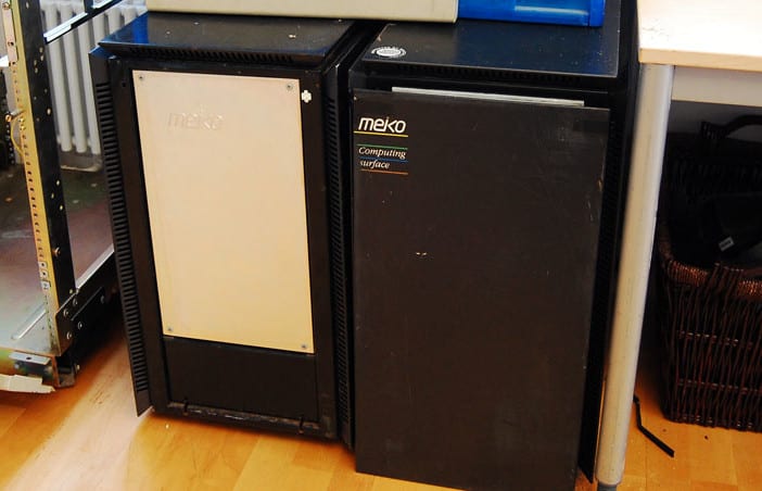
Meiko were a British company who manufactured massively parallel supercomputers, which were initially built using all transputers, but they also later switched to other architectures for compute, such as i860 and Sun SPARC, while like Parsytec retaining transputers for communication.
A Computing Surface node is a large black monolith a little under half the size of a washing machine. Two nodes can be seen pictured above, with the one on the left missing its front door, behind which is another panel which provides access to a card frame. Installations could comprise of anywhere from one to a large number of nodes, with upgrades as simple as buying additional nodes and hooking these into the transputer link network.
Above can be seen a Computing Surface board with four transputers and you might typically have, say, four of these boards fitted in a node, for a total of 16x transputers available for compute. Along with also other boards, providing I/O such as video for graphics. The earliest Computing Surface nodes would be interfaced with an external host, such as a PC fitted with an ISA link adapter. Later nodes went on to integrate a Sun workstation, hence could be connected via an Ethernet network.
The Computing Surface software environment is the most complex of all the systems covered so far and included the CS Tools suite, which featured a Run Time Executive (RTE) that provided operating system facilities to applications, along with things such as Virtual Computing Surfaces (VCS), a multi-user resource management system, and the Computing Surface Network (CSN) software, which abstracts the network to hide physical connectivity details from the programmer.
The Computing Surface is probably the least appropriate platform for starting out with, not just because of the complexity and tracking down Meiko software is proving quite tricky, but also because the two nodes in the collection were stored for some years in a damp basement, hence restoration is likely to be a long process and potentially fraught with difficulties.
So where would be a good place to start?
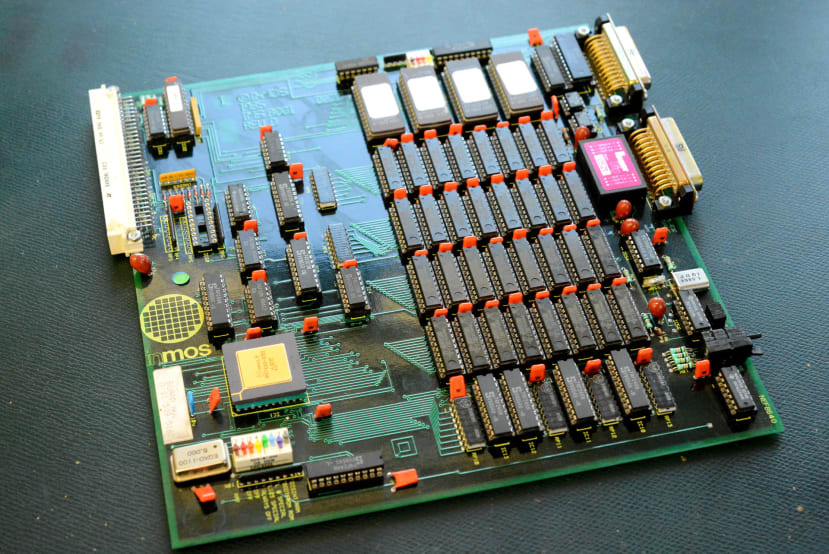
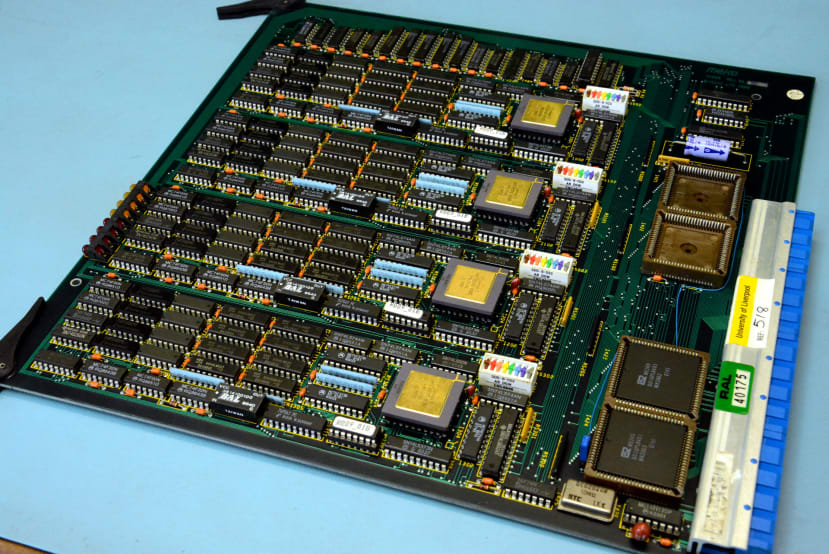
IMS B001
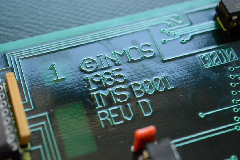
The INMOS B001 was the first in a family of compatible transputer evaluation boards and dates back to around 1985. A simple design which integrates a single transputer, 64KB RAM and 128KB ROM, plus a dual-UART, this is a much better fit and what we plan to start out with.
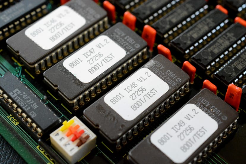
Here we can see a bank of four EEPROMs and these are used to store a monitor program, which will allow us to interact with the system with nothing more than a terminal (or terminal emulator) and carry out tasks such as testing the memory and links, for example.
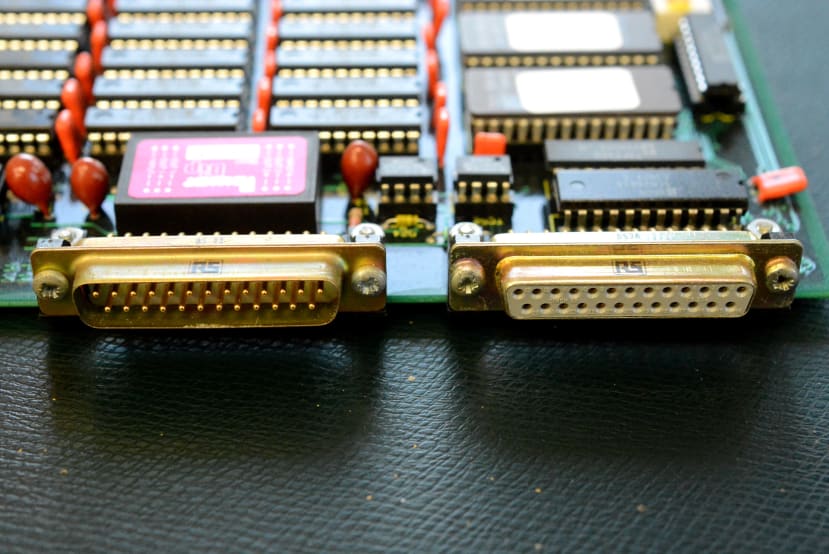
Above we can see the two serial ports for connection to a terminal and/or host computer.
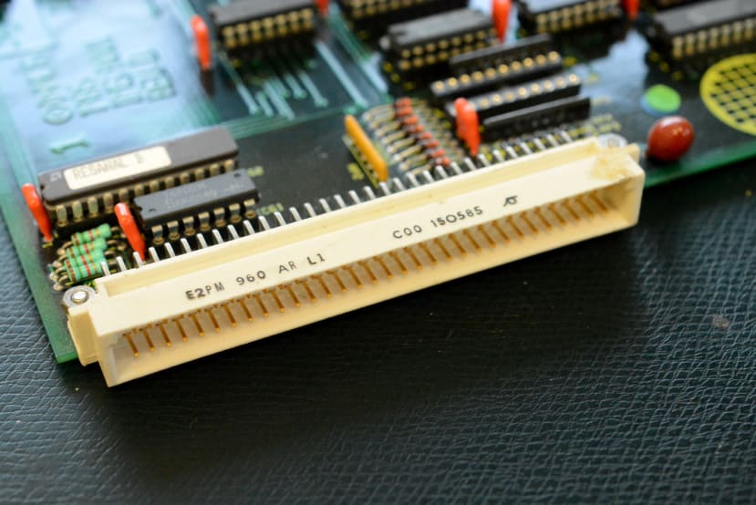
Finally, here is the DIN 41612 connector — the same as used by VME bus and Multibus II systems — which will be used to supply power. In addition to which, this carries transputer link I/O, along with PIO and various other useful signals. Hence this could be used to interface additional external transputers, with either the B001 or the external board or system acting in a control capacity.
Next steps
In the next article in this series we’ll make up a mating DIN connector to supply power to the board and source cables to interface with the serial ports. We’ll also try to track down some suitable software, which may end up being DOS based, as a lot of the INMOS software was distributed for use with a PC host. Finally, we’ll see if we can bring the almost 40 year old board to life and explore the early transputer evaluation platform.
Comments