Give your Robot the Mobility Control of a real Mars Rover: Part 2
Follow article
 Dave from DesignSpark
How do you feel about this article? Help us to provide better content for you.
Dave from DesignSpark
Thank you! Your feedback has been received.
Dave from DesignSpark
There was a problem submitting your feedback, please try again later.
Dave from DesignSpark
What do you think of this article?

Part 1 covered the theory behind PID control – a widely used method of ensuring that the mechanical output of an actuator (speed, position, etc) matches the value demanded by its controlling program. I have shown how the complex theory translates into relatively simple arithmetic capable of running on a basic microcontroller. Now let’s look at some real code written for a two-wheel buggy robot driven by continuous-rotation servomotors. I’ve used a Microchip 16-bit dsPIC33 Digital Signal Controller – a PIC24 microcontroller with DSP extensions – but most of the practical issues are applicable to projects based on other microcontrollers.
Capturing the Wheel Rotation Data
The device for sensing wheel rotation speed consists of two parts: the wheel itself with 32 radial slots and a reflected IR beam module fixed to the chassis and lined up with the slots (Fig.1). The principle of operation is simple.
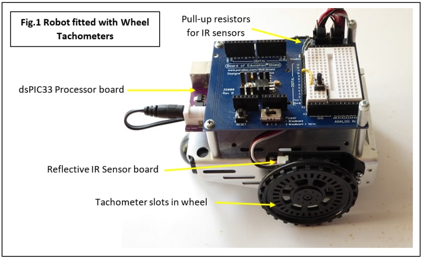
The sensor module consists of an Infrared (IR) LED and photodiode side-by-side and pointing at the wheel slots. As the wheel rotates, the beam passes through a slot and is thus not seen by the photodiode; but it is reflected back to the diode between the slots. The result is a pulse train whose repetition rate is proportional to the wheel’s rotational speed. We need a way to measure this rotation rate and fortunately most modern microcontrollers have built-in hardware called ‘Input Capture’ units for this purpose (Fig.2).
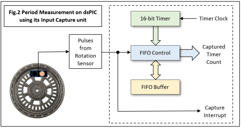
In principle you could measure speed by using a counter clocked by the sensor directly. Sampling the counter at fixed intervals and clearing it each time would give a value for speed. The problem is that at slow speeds the sampling interval would have to be way too long to capture a significant count. This can be overcome by turning things around: increment the counter with a fast clock and sample or ‘capture’ its value using the sensor pulses. By this means we get a measurement for the pulse period instead. The dsPIC Input Capture (IC) unit features all the hardware necessary and just needs a few lines of assembler code to make it work. Unfortunately, there is a complication – there are two independent IC units available on the particular chip I’m using, but one of the timers is needed for another function. There is a solution: the remaining timer can be shared thanks to other some hardware in the IC unit. Two IC units are both set up to use Timer 3 in this case, which counts continuously from 0000 to FFFF, overflows to 0000 and repeats. Here is the compromise: the counter cannot be restarted at the beginning of each sample period because the two units will be sampling at different times to each other (Fig.3).
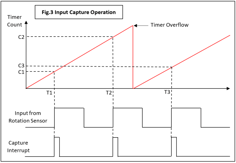
The ramp waveform represents the timer count climbing from 0000 to FFFF and repeating. The pulse waveform from a rotation sensor is shown underneath ‘capturing’ the timer count on every rising edge. The input capture hardware saves this ‘snapshot’ in its FIFO buffer and simultaneously generates an interrupt to the processor.
Calculating the Speed
Now the interrupt service code takes a count value stored from a previous interrupt, subtracts it from the latest one, and obtains a number representing the sensor pulse period. In the diagram, snapshot counts C1, C2 are taken at times T1, T2 and C2 – C1 corresponds to interval T2 – T1. Easy. But there are two issues concerning what happens when the wheel first starts turning:
- There is no valid ‘previous count’ value when the first sensor interrupt occurs, so the first calculated speed will be wrong.
- There is a minimum speed limitation in that the sensor pulse period cannot be longer than that taken by the timer to count from 0000 to FFFF. There is also a maximum speed limitation but that is unlikely to be a problem!
Both of these mean that the first few speed values calculated after the robot starts moving are likely to be invalid. Not much can be done about this, except to have the PID control code ignore those first values by starting the motor and running it ‘open-loop’ for an estimated time from rest until the sensor values come into range. Referring back to Fig.3, there is a further problem, but one that can be fixed. Consider the speed calculated at time T3. The interval from T2 to T3 straddles the counter overflow so C3 – C2 will provide the wrong answer. Fortunately, this situation can be detected by the software, C3 being less than C2, and a correction factor applied. Normally the latest value is larger than the earlier one as with C1 and C2.
Actual Code
The basic interrupt service routine for my dsPIC processor which calculates speed and the three ‘raw’ P, I and D values without scaling and K factors is given below in Listing 1.
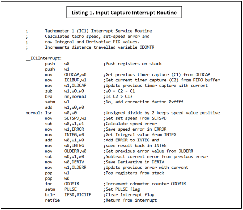
This is the interrupt routine for one of the two rotation sensor channels built into FORTHdsPIC, my own embedded control programming language. Despite being in dsPIC assembler (‘bare-metal’) code, it should be easy to see how the original complex PID equation just comes down to a few adds and subtracts. This code executes with every sensor pulse, calculating and saving the raw PID values in variables ready for the main program to process. I’ll cover this main program, which takes these variables and calculates the motor control value, in Part 3 of this series. The interrupt routine also contains a single line of code that performs a vital navigational task – it provides odometry.
Odometry
The wheel rotation sensor doesn’t just provide speed information (Tachometry): by counting the pulses you get a measure of distance travelled (Odometry). That’s what the line ‘inc ODOMTR’ does in Listing 1. Anyone who has driven a car or motorcycle will recognise an odometer: it’s that miles-travelled digital readout on the dashboard. On a robot it can have a vital role in the mobility system. In this case, the ODOMTR variable is incremented on each sensor interrupt which corresponds to a wheel rotation of one slot, giving a total of 32 for each complete revolution. To find the distance travelled over a single slot period, just divide the wheel circumference πD by 32, where D is the wheel diameter. These Parallax Encoder wheels have a diameter of 66mm so the odometry resolution is 6.4mm. My robot uses differential-speed steering and needs speed data from each wheel for straight-ahead movement, and distance-travelled data to perform accurate turning manoeuvres. More of this in Part 3.
Quadrature Encoders
The simple rotation sensor described above has one rather obvious limitation: it can’t tell which way the wheel is rotating. By adding another photosensor, direction of rotation information can be extracted. The second sensor is aligned so its output pulse waveform is precisely 90° out of phase with the first (Fig.4).
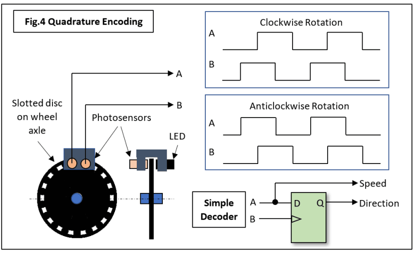
A simple D-type flip-flop is all that’s needed to decode these signals. Most recent microcontrollers designed for motor control usually have a pair of QE channel inputs with the necessary hardware on-chip. My robot doesn’t require a ‘reverse gear’ so a simple tachometer will suffice, but planetary rovers need to be able to go backwards.
Next Time in Part 3
I’ll talk about the motor-driving end of the PID algorithm and how the robot navigates by ‘dead-reckoning’. Finally, some practical problems – what happens on rough terrain as the load on the motors varies? Find out how a design flaw in the mobility control system of the Mars Curiosity rover led to its wheels being damaged. Even rocket scientists can’t think of everything!
If you're stuck for something to do, follow my posts on Twitter. I link to interesting articles on new electronics and related technologies, retweeting posts I spot about robots, space exploration and other issues.
Comments