Fun with ALICE and Op Amps
Follow article
 Dave from DesignSpark
How do you feel about this article? Help us to provide better content for you.
Dave from DesignSpark
Thank you! Your feedback has been received.
Dave from DesignSpark
There was a problem submitting your feedback, please try again later.
Dave from DesignSpark
What do you think of this article?
Completing the summing amplifier exercise with ADALM1000.
In the post Learning about Op Amps I followed the online tutorials from Analog Devices using the ADALM1000 and ADALP2000, until I hit a hurdle completing the summing amplifier activity; to complete the activities in the post I had been using the Pixelpulse2 software which was going well until I realised I needed to be using ALICE.
To complete this exercise I needed to first get to grips with ALICE basics.
Active Learning Interface for Circuits and Electronics
ALICE is provided by Analog Devices and the name comes from Lewis Carroll’s novel, 'Alice's Adventures in Wonderland', and is for students to explore the 'strange and wondrous world' of electronics, circuits and electrical engineering with the ADALP2000 companion kit of the ADALM1000.
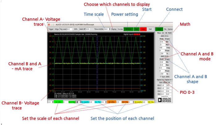
Like PixelPulse2, ALICE also has the capability of sourcing and measuring voltage and current. However ALICE has the upper hand as this also has the capability to control the four separate PIO pins of the ADALM1000, amongst other features.
There are several versions of ALICE available and for the exercise I used the oscilloscope version, but there is also a spectrum analyser version which I haven’t had chance to use yet.
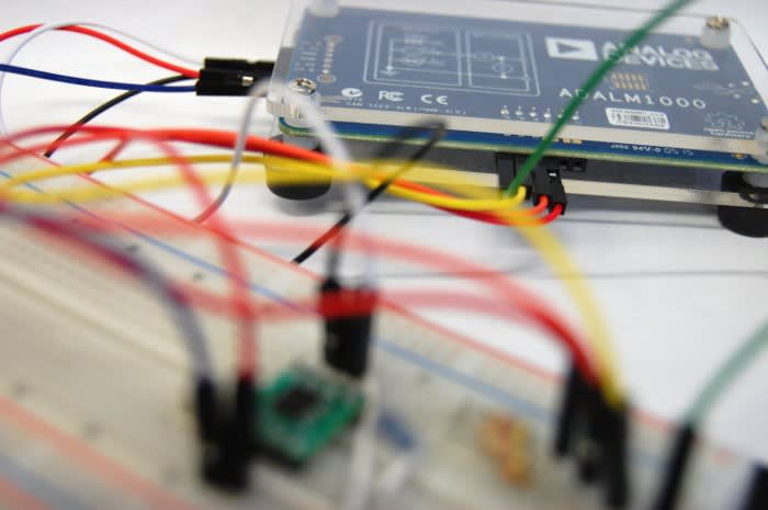
To begin with I followed the first example in the ALICE section of the Analog Devices website, using an NPN transistor. Once I had configured the software settings as instructed I then connected the VCC and GND pins, along with channel A and B. I set the program running and found I had the expected results.
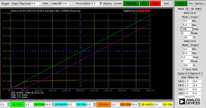
The green line is the voltage measurement at the point of the 100k resistor, the purple line is the is the voltage drop measurement after the resistor and the orange is the voltage measured on the base of the transistor.
After completing the above exercise and confirming I understood the very basics, I decided next to repeat the last project which I completed using PixelPulse2, the inverting amplifier. However, this time I would use ALICE and then confirm that I got the same results..
The graph above shows exactly what I would have expected to see: the green line is the input voltage and the orange is the output, showing that the output voltage had been amplified but with a phase shift of 180°.
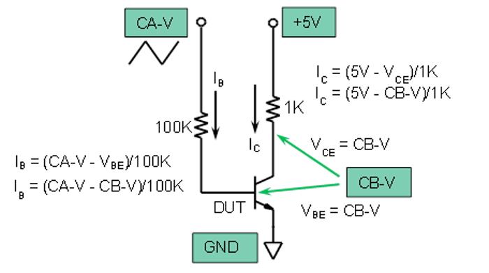
Completing the Summing Amplifier Exercise
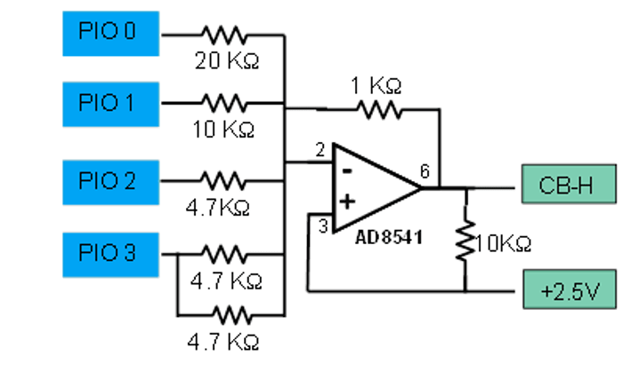
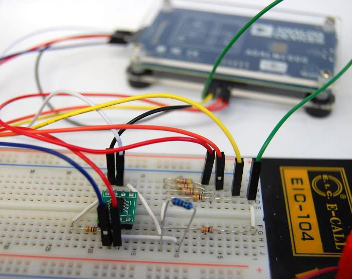
The circuit shown above is a summing amplifier which can be used as a digital analogue converter. The ADALM1000 has pins labelled PIO 0-3 which can be set to a high, low or high impedance state: in other words they can either be connected to 3.3V, GND or be left floating.
For this exercise I needed to complete a table of calculations for the predicted output voltage. This was the part where I had to do a little bit of research, since we've not yet covered operational amplifiers in college. I found some very useful tutorials online showing how to calculate Vout for inverting and summing amplifiers. I could treat the circuit as an inverting amplifier for the first part of the calculations, with just one input. For the measurement part of this I would set three of the inputs to HI-Z mode, while I gathered readings with the fourth pin set both high and low.
The equation below is that used to calculate the output voltage of a summing amplifier circuit.
- Vout = Rf x ((V1/R1) + (V2/R2) + (V3/R3))... etc
Rf in this example would be the 1KO feedback resistor used.
When a pin is set at 0, this represents that this pin has been pulled to GND. For calculating the with the binary 1s and 0s I substituted V for either 0 or 3.3[V](the operating voltage of the PIO pins in their 'high' state). For example, for binary 1000 I would use the following equation:
Rf x ((3.3/20) + (0/10) + (0/4.7) + (0/2.35)) = - Vout
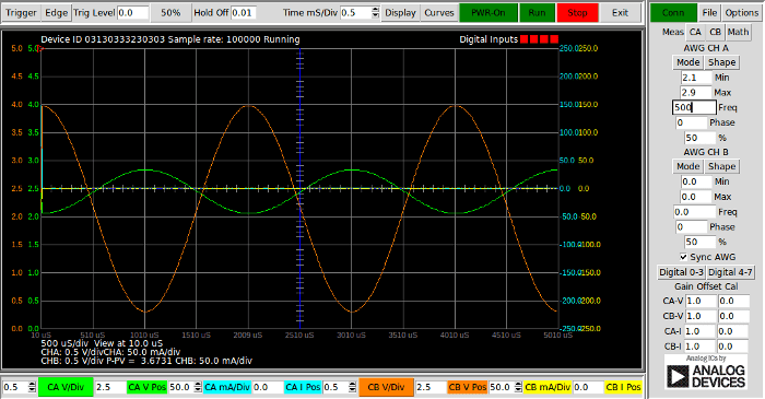
I substituted each value into the above equation for all 16 combinations of 0s and 1s in the table of binary code. When this was complete I then proceeded to measure the actual output voltage using the ALICE software.
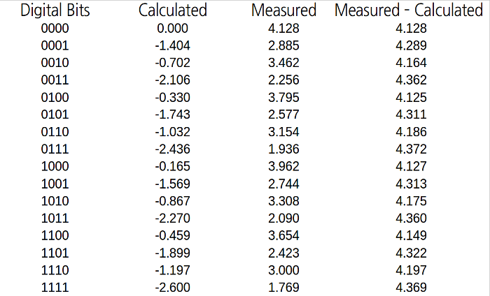
At first glance the measured and calculated results seem to have no correlation at all. Initially this was not obvious until the calculated results were subtracted from the measured. When I had repeated this calculation for all 16 bit combinations it became apparent that the results were almost exactly the same as the measurement for 0000. It soon became obvious that the calculation would provide the difference from the maximum output voltage to what the measured result should be.
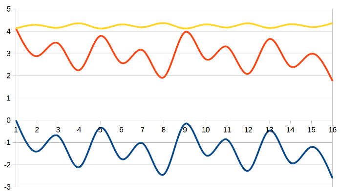
The reason the maximum voltage line was not perfectly flat was due to working backwards, which incorporated any variation in actual resistance due to tolerance. As you can see from the graph above the measured (orange) line follows an identical shape to that of the calculated (blue) line.
Learning New Tools
After a brief trip with ALICE down the rabbit hole I can honestly say it wasn’t all that mad. After accustoming yourself with the software controls it's fairly easy to use and has lots of useful capabilities.
This time I only had chance to work with the ALICE oscilloscope, but there is also the spectrum analyser which I look forward to trying out!
Comments