Experimenting with Electrocardiogram Electronics
Follow articleHow do you feel about this article? Help us to provide better content for you.
Thank you! Your feedback has been received.
There was a problem submitting your feedback, please try again later.
What do you think of this article?
Looking at ECGs with the BES-AFE-1 Breakout Board Kit and Analog Discovery 2.
In this post we’re going to look at both the science and electronics behind electrocardiograms (ECGs) and have a go at putting this theory to the test, using the BES-AFE-1 module and Analog Discovery 2 (134-6480) oscilloscope.
I’ve always loved anything medical and since sixth form when I studied Human Biology I love throwing myself into this kind of subject. What I find is particularly great about this is that,not only does this entail some research into the medical aspects of ECGs, but this also combines electronics with it!
What is an ECG
Most people have encountered the term ECG at some point in their lives, whether this has been from personal experience or from watching medical dramas. ECGs are predominantly carried out for cardiology testing — these are a view of a trace of electrocardiography, which is the process of recording electrical activity in the heart over a certain period of time. These are used in certain situations where it is necessary to gain a better understanding of how the heart it functioning, some of these situations include:
- Suspected heart attacks
- Fainting
- Seizures
- Stress testing
- Preoperative monitoring
In order to produce an electrocardiogram trace, electrodes are placed on the skin of the person under observation. These electrodes detect the minute electrical changes on the skin, which are caused by the electrophysiological pattern of depolarising and reploarising of the heart muscle during each heartbeat.
Cardiac Conduction
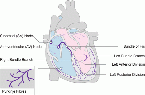
The heart has its own electrical conduction system which makes electrocardiagram readings possible; this is known as the cardiac conduction system and consists of five elements:
- The sino-atrial node (SA)
- The atrio-ventricular node (AV)
- The bundle of His
- The left and right bundle branches
- The Purkinje fibres
This cardiac conduction system controls the relaxation and contraction of the four chambers of the heart, both the left and right atriums and ventricles. The electrical stimulus from each of the above mentioned elements triggers either another impulse or the emptying/refilling of the atria and ventricles, creating a domino effect between these.
To describe the discharge of one of these electrical stimulus’s we call this depolarisation, the recharge is referred to as repolarisation. These stages are incredibly important as they are what contribute the three stages of a single heartbeat are:
- Atrial depolarisation
- Ventricular depolarisation
- Atrial and ventricular repolarisation
Graphical Representation
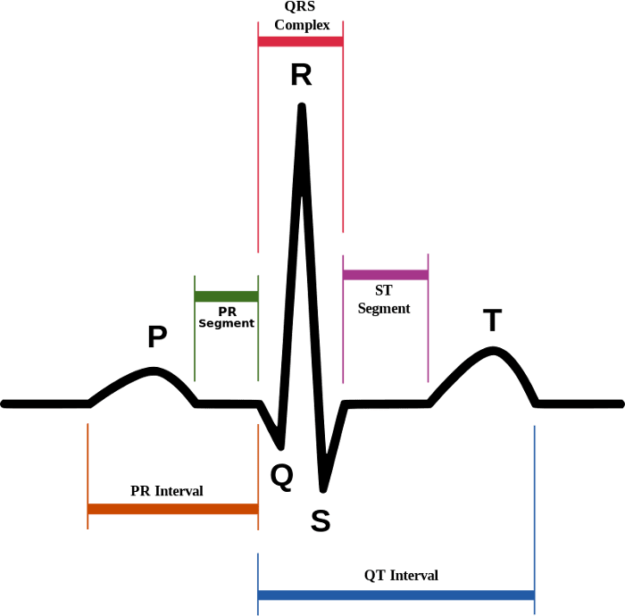
An orderly pattern of overall magnitude and direction of this depolarisation is captured, and a graph of this as a voltage with respect to time produces an electrocardiogram.
On the diagram above the ‘P wave’ indicates the atria contracting to pump blood. The following section of the trace which troughs and then suddenly peaks is called the QTS complex and indicates that the ventricles are contracting to pump out blood. The next short segment is referred to as the ST segment, which illustrates the time from the end of a contraction of the ventricles to the beginning of the rest period before the ventricles contract again for the following heart beat. The final section of the trace is the T wave and this shows the rest period of the ventricles.
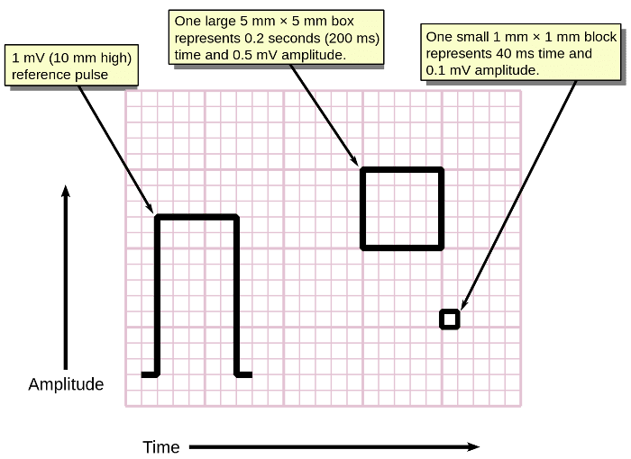
ECGs have a standardised scale: the Y-axis is the amplitude with the X-axis being time. One of the small boxes on the graph paper usually represents 0.1mV of amplitude and 40ms of time, the larger boxes which consist of 5x5 small boxes therefore represent 0.5mV amplitude and 0.2 seconds of time.
ECG Leads
In order to carry out an ECG you need a number of electrodes to analyse electrical events within the heart from a number of different angles, and in my opinion the terms used when describing aspects of an ECG can be somewhat confusing. Knowing that an ECG uses electrodes placed on the surface of the skin to gain these views of the heart I automatically assumed that a ‘12-lead’ ECG would consist of 12 physical electrodes or ‘leads’ — unfortunately I was wrong. At this point I had to ask myself what is a ‘lead’ in terms of an ECG and how many wires (electrodes) do they use?
An ECG electrode is a conductive pad which is attached to the skin and enables the recording of electrical currents within the body, whereas an ECG lead is the term used to describe the graphical description of the electrical activity of the heart and is created by analysing several electrodes — the leads of an ECG all analyse the same electrical events but from different angles.
I find it easier to look at it like so: a 12-lead ECG uses 10 electrodes placed on the surface of the skin: 4 on the arms and legs and 6 around the intercostal muscles. This produces a graphical representation of electrical events from within the heart from 12 different angles.
Different numbers of ‘leads’ are different types of monitoring, for example:
A 3-lead ECG can be used for continuous monitoring of the heart. This can monitor heartbeat, heart rate and rhythm in critical situations, an example of which would be when a patient is under anaesthesia. Here four electrodes produce three different views of the heart.
A 1-lead ECG just gives you a single view of the heart. These are used in very basic heart monitoring such as checking for arrhythmias or educational/research purposes, consisting of only three electrodes. 1-lead ECGs can be used to accomplish a full 12-lead ECG in a sequential manner, the difference between this and a 12-lead ECG is that a 12-lead produces the 12 different views of the heart in a simultaneous manner.
Carrying out an ECG
Early ECGs used analogue electronics where the signal could drive a motor to print said signal on paper. In modern electrocardiographs we use ADCs to to convert the signal to digital so that this can be manipulated with digital electronics.
In order to produce an electrocardiogram electrodes are placed on the skin of the person under observation. An electrode is a conductive pad in contact with the body which makes an electrical circuit with the electrocardiograph. These electrodes detect minute electrical changes on the skin which are caused by the electrophysiological pattern of depolarising and repolarising of the heart muscle during each heartbeat.
Using electrodes, the overall magnitude and direction of the hearts electrical potential is measured from several different angles and is recorded over a period of time.
When designing an ECG machine it can be very difficult for the ADC to pick up the heart’s electrical activity due to the signal itself often being around a 1/10th of a millivolt on the surface of the body. Noise and offset also create concerns when attempting to amplify such signals because both line interference (from AC power) and contact induced offset/baseline wander (e.g. from breathing and movement) will be many orders of magnitude larger than the signal itself.
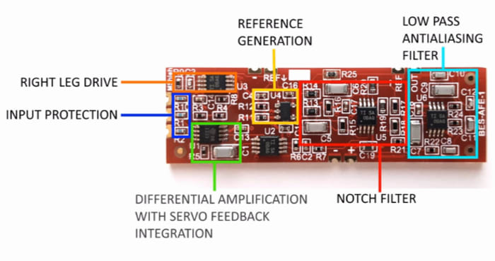
The fundamental component to an electrocardiograph is the instrumentation amplifier which is responsible for taking the voltage between the leads and then amplifying the signal. As the signal is such a low voltage this necessitates a low noise circuit and here instrumentation amplifiers are key. There are additional components to electrocardiographs:
Safety features which include voltage protection for the patient and operator. As most ECG machines are mains powered, it is conceivable that either person could be subjected to a voltage capable of causing death. In addition to this the heart is sensitive to the AC frequencies typically used for mains power (50Hz in the UK).
Defibrillation protection. When used in healthcare an ECG machine may be connected to a patient whom requires defibrillation, because of this the electrocardiograph needs to protect itself from this source of energy.
Electrostatic discharge is similar to defibrillation discharge and requires voltage protection up to 18,000 volts.
Right leg drivers are additional circuitry which is used to reduce common-mode interference (typically the 50/60Hz mains power).
BES-AFE-1
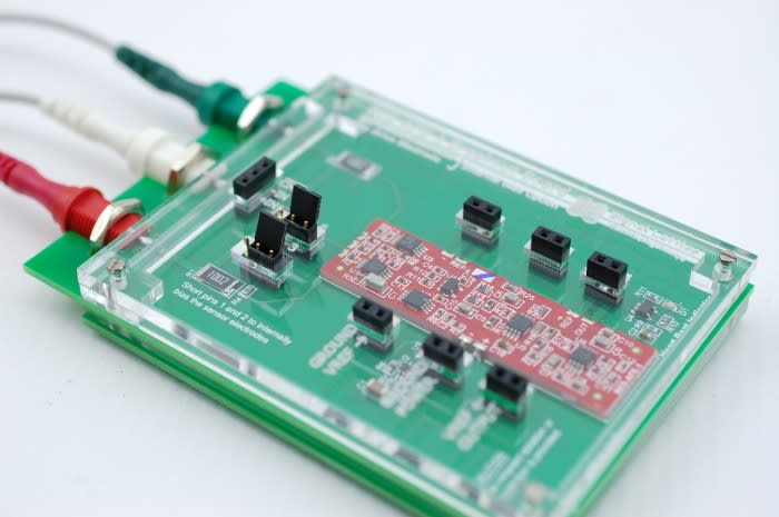
This is a Crowd Supply funded module which has been designed to offer the user a low noise, low offset, and low power solution in a compact easy-to-use form factor. With the benefits of built-in right-leg drive, baseline wander rejection, notch filtering, and anti-aliasing. In many applications such as heart rate monitoring, the module can reduce or even remove the need for filtering while avoiding unacceptable distortion from inadequately designed analogue circuitry.
As mentioned previously even though this device is a 1-lead electrocardiograph this has the capabilities to produce a 12-lead trace sequentially. Because of this and the capabilities mentioned above, this attracts a varied target audience of:
- Makers/Hobbyists
- Students
- Teachers
- Engineers
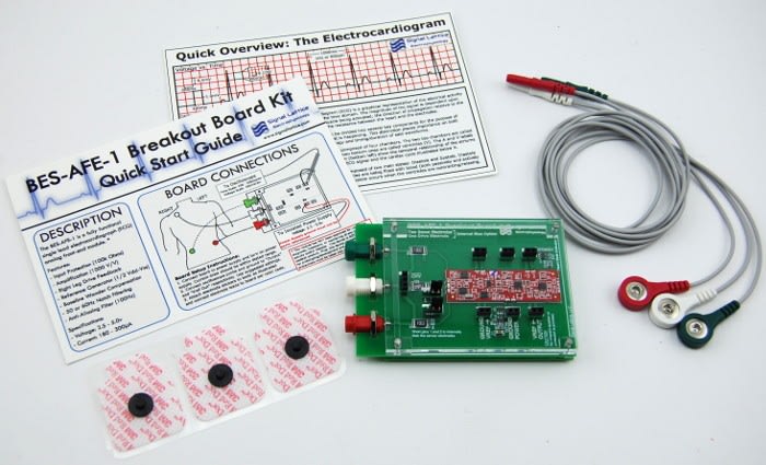
In the BES-AFE-1 Breakout Board Kit you get:
- The breakout board with a BES-AFE-1 module already mounted.
- 3 electrode cables
- 12 electrode pads
- Quick Start Guide
- Quick Overview: The Electrocardiogram
With the Quick Start Guide you can be ready to start in as little as a minute!
Specifications
- Voltage Supply: Single and dual rail ranging from 1.8v (±0.90) to +5.5v (±2.75v)
- Current consumption: 180µA to 290µA. Typical 220µA @ 3.3v
- Internal Reference: (Vdd-Vss)/2 which can be easily overridden by the user with an external reference
- Bandwidth: 100Hz
- Low-Pass: First order at 0.8Hz
- Notch: 50Hz with >20dB Notch Depth
- High-Pass: Fourth Order Bessel at 100Hz, First Order at 96.6Hz on secondary gain stage
- Size: 50.8mm x 15.24mm
- Design Criteria: This module has been designed to preserve waveform morphology and maximize noise immunity at the expense of bandwidth and absolute gain accuracy.
Plug and Play!
Since I’d done a fair amount of reading up about ECGs and how they work I thought I may as well go ahead and have a go at taking my own ECG. I followed the quick start guide which came in the box and placed the three electrodes on my skin; white towards my right shoulder, green to my right side and red to my left side.
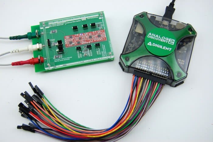
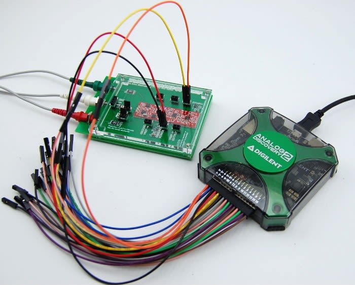
As I was using the Analog Discovery 2, I set the power supply channel to positive 3.3v and negative off, doing so knew I could expect a current draw in the region of 220uA and connected the AD2 to the breakout board as follows:
Scope Ch1 Positive — Output
Scope Ch1 Negative — Vref Out
V+ Power Supply — Power
GND — GROUND
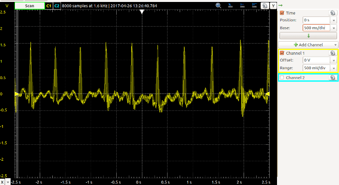
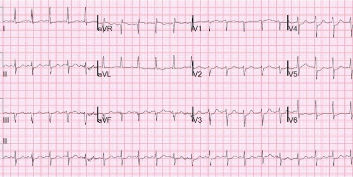
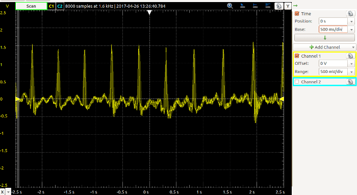
Once I powered this on I then opened the scope and set this to 500mV/div and also set the time base to 500ms/div. Below we can see the trace of the ECG.
By no means do I feel like I could interpret the trace – I’m pretty certain you need a medical degree to do that! However, I do feel that the output is clear and it certainly looks accurate.
I’ve enjoyed using the BES-AFE-1 breakout board and learning more about the biology and electronics behind ECGs. I would really love to work with more platforms which combine both electronics and medicine, perhaps I need to consider looking into medical electronics!


Comments