Edge Enabling a PLC with Rock Part 2: Software
Follow article
 Dave from DesignSpark
How do you feel about this article? Help us to provide better content for you.
Dave from DesignSpark
Thank you! Your feedback has been received.
Dave from DesignSpark
There was a problem submitting your feedback, please try again later.
Dave from DesignSpark
What do you think of this article?
Using a Rock 4 C+ to edge-enable an RS PRO PLC for smart automation.
In Part 1 in this series we took a look at the hardware selected and how we would integrate a simple RS PRO programmable logic controller (PLC) with a Rock single-board (SBC) using Modbus, to create a powerful edge compute enabled platform for industrial automation.
In this second and concluding article in the series we will now move on to software installation and a simple demonstration using Node-RED for Modbus communications.
Software installation
Official operating system (OS) support for Rock 4C+ (249-3158) includes Android, Debian and Ubuntu, with images made available for download via the OKdo Software Hub. We opted for Debian and with both this and Ubuntu, there are command-line interface (CLI) — a.k.a. “headless” — and desktop versions. Since we have no need for a graphical desktop and will be accessing the SBC over the network, we went with Debian Bullseye cli for Rock 4C+. Of course, it would also be possible to attach a keyboard, monitor and mouse and use the KDE desktop version for local access.
Note that we used an Ubuntu desktop system to write out the image to a Micro SD card.
Debian
With the Debian CLI image downloaded this needed to be uncompressed, which can be done on Linux using the XZ Utils. If these are not already installed, they can be installed on Ubuntu with:
$ sudo apt install xz-utilsThe image was then uncompressed with the command:
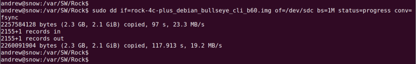
$ unxz rock-4c-plus_debian_bullseye_cli_b60.img.xzThe resulting file was 2.2GB in size and we wrote this out to a Micro SD card with:
$ sudo dd if=rock-4c-plus_debian_bullseye_cli_b60.img of=/dev/sdc bs=1M status=progress conv=fsyncAs ever, taking great care with the of=/dev/XXX argument to be certain that this corresponds to the SD card and not another storage device, which could very easily result in irrecoverable data loss!
Once written out the card was inserted into the Rock 4 C+ and a keyboard, monitor and USB-C power supply connected. Upon booting we then logged in with username radxa and password radxa, following which performed a customary update of the OS packages with:
$ sudo apt update && sudo apt dist-upgradeWe also changed the hostname to plc, by updating the appropriate entries in /etc/hostname and /etc/hosts. Since mDNS is already configured in the provided Debian image, following a reboot we were then able to connect from the Ubuntu desktop machine using:
$ ssh radxa@plc.localNode-RED
We next proceeded to set up Node-RED, which is described as “a programming tool for wiring together hardware devices, APIs and online services in new and interesting ways”, and providing “a browser-based editor that makes it easy to wire together flows using the wide range of nodes in the palette that can be deployed to its runtime in a single-click.” Importantly, Node-RED includes “nodes” which make it easy to communicate with Modbus devices.
Note that we could instead have used a simple Python, Node.js or similar script with an appropriate Modbus package, but Node-RED makes it easy to quickly prototype powerful solutions, which could optionally later be implemented directly in a text-based programming language.
We started by installing Node.js — which is the main dependency for Node-RED — and for this we opted to install a recent build from NodeSource, rather than using the older Debian OS package. To do this we followed the instructions provided for Debian Linux and went with Node.js 20.
First we set up the NodeSource package signing key, so that packages could be verified.
$ sudo apt install -y ca-certificates curl gnupg

$ sudo mkdir -p /etc/apt/keyrings

$ curl -fsSL https://deb.nodesource.com/gpgkey/nodesource-repo.gpg.key | sudo gpg --dearmor -o /etc/apt/keyrings/nodesource.gpg
Following which the Node.js 20 repository was configured.
$ NODE_MAJOR=20

$ echo "deb [signed-by=/etc/apt/keyrings/nodesource.gpg] https://deb.nodesource.com/node_$NODE_MAJOR.x nodistro main" | sudo tee /etc/apt/sources.list.d/nodesource.list
Then Node.js could be installed.
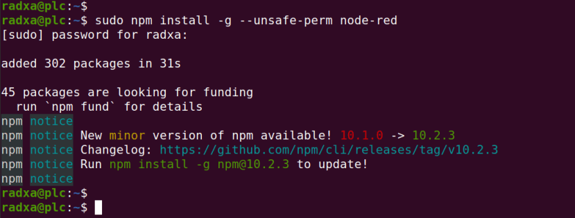
$ sudo apt update && sudo apt install nodejs -yFinally, we could now use the Node.js package manager, npm, to install Node-RED.
$ sudo npm install -g --unsafe-perm node-redNode-RED basics
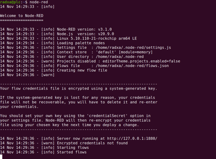
Running Node-RED is as simple as entering into a terminal window:
$ node-redAbove we can see debug output which indicates the versions of Node-RED, Node.js and Linux kernel. We can also see that our settings and “flows” (applications) are stored in a hidden .node-red sub-directory. By default anyone who can access the Node-RED web interface can make changes to flows and if we wanted to secure this, we could configure a username and password via the .node-red/settings.js file. Similarly, by default our Node-RED instance will bind to (be accessible via) all available network interfaces and we could restrict access by configuring the same file.
See the Node-RED documentation for details of configuration options.
The text printed to the terminal instructed us to connect to http://127.0.0.1:1880/, but this will only work where we are running a web browser on the same machine that we’ve installed Node-RED to. So in our case the URL to use from the desktop system was instead http://plc.local:1880.
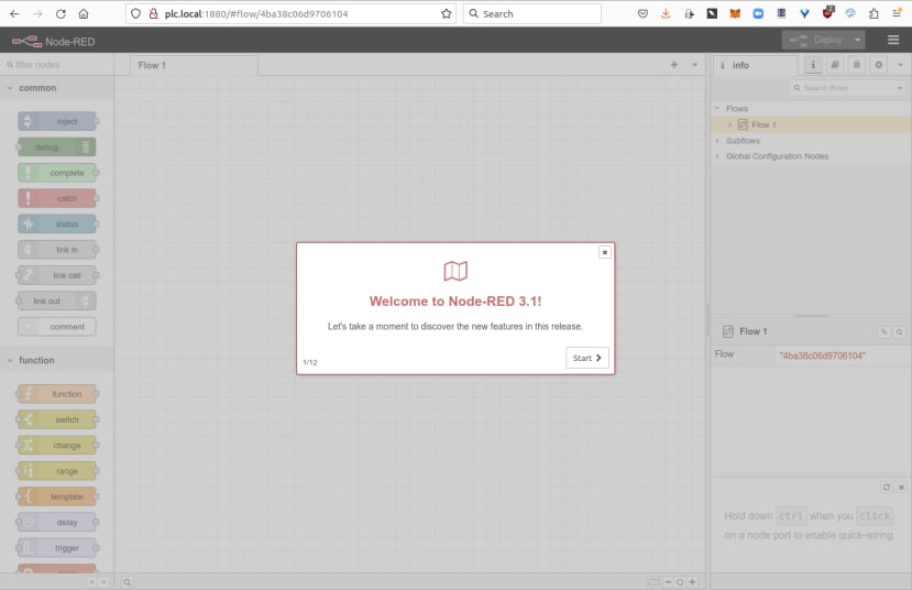
Upon loading the Node-RED web interface the first time we are greeted with a welcome panel which introduces new features.
Modbus parameters
Before we can get on to creating a Node-RED flow to integrate our RS PRO PLC (917-6370) , we need to know the Modbus parameters.
First of all we will be communicating with Modbus RTU via a serial port and in our case we’ll be using the RS PRO USB cable (917-6395) , which is more typically used with the PLC programming software.
Another option would be to equip the Rock 4 C+ with an RS-485 serial interface — e.g. plugged into a USB port — and then use the optional DIN rail mounted RS-485 PLC module (917-6392) . This might be preferable if we had additional Modbus RTU devices that we also wanted to communicate with, or alternatively if we we’d like to position the PLC far away from the Rock SBC, since RS-485 can operate over much longer distances than USB.
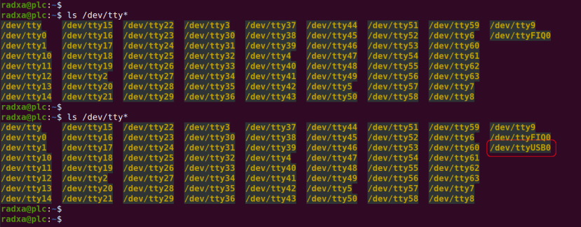
By comparing the files prefixed with tty in the /dev directory, before and after plugging the PLC USB cable into the Rock 4 C+, we could ascertain its device name. Above we can see that the serial adapter has enumerated as /dev/ttyUSB0. From the PLC documentation we know that the default communications parameters are 9600 baud, no parity and 1 stop bit, so we’ll need to use these settings in Node-RED when connecting via the serial port.
In order to be able to access the serial port we needed to add our user to the dialout group:
$ sudo usermod -a -G dialout radxaTo pick up the group we then had to log out and back in again, and re-start Node-RED.
Each Modbus RTU device has a unique address between 1 and 255. The RS PRO PLC default Modbus address is 1, so this is what we’ll need to use when communicating with it. Although the address can be changed, since in a production environment we might have a single RS-485 bus with numerous devices connected to it and each would need a unique address.
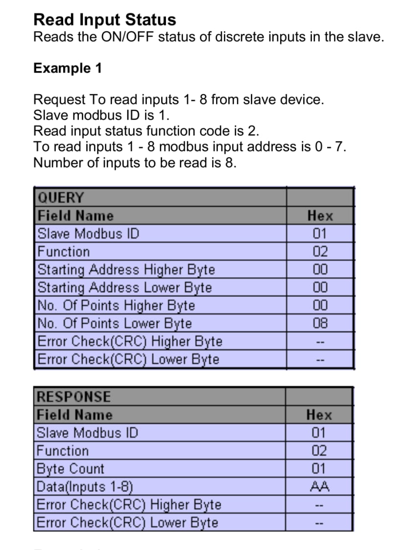
In Part 1 we briefly talked about Modbus Function Codes, notably FC2 “read a discrete input” and FC5 “write single coil”, which we’ll need to use to read a digital input and write to an output. Along with which we’ll also need the register addresses of the input or output in question. In our case the address used with each is 0. When reading the inputs we can also specify quantity 8 to read the status of all the PLC inputs in a single operation.
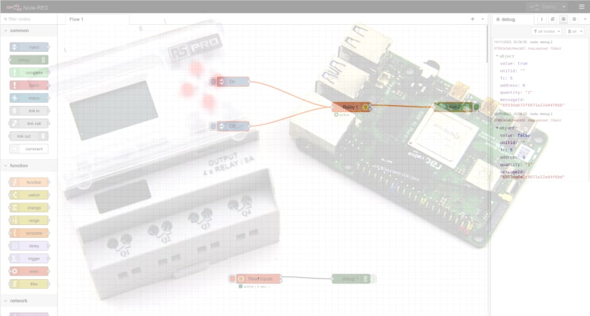
Test flow
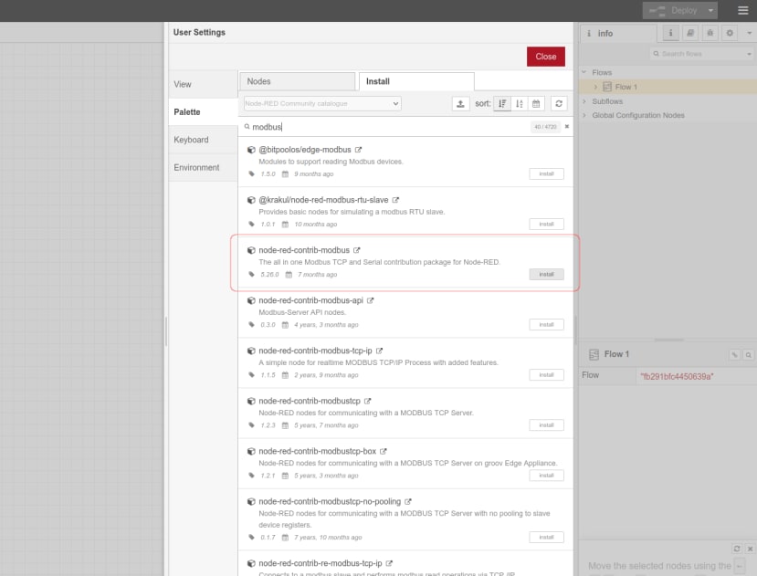
On the left-hand side of Node-RED we have the palette, where all the various nodes are organised by category. However, by default this does not include any Modbus nodes and so these had to be installed via Main Menu (three bars top-right) → Manage Palette. From here we searched for and installed node-red-contrib-modbus.
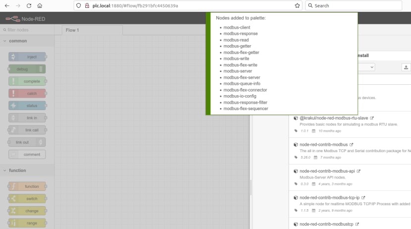
Once installed we had to stop and restart Node-RED in order for it to pick up the new nodes.
Reading inputs
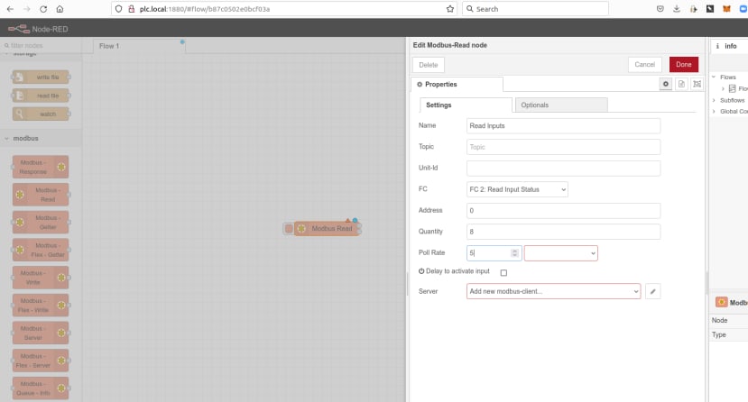
To read the PLC digital inputs we started by dragging a Modbus Read node from the palette, dropping this onto the canvas, then opening it and filling in the parameters.
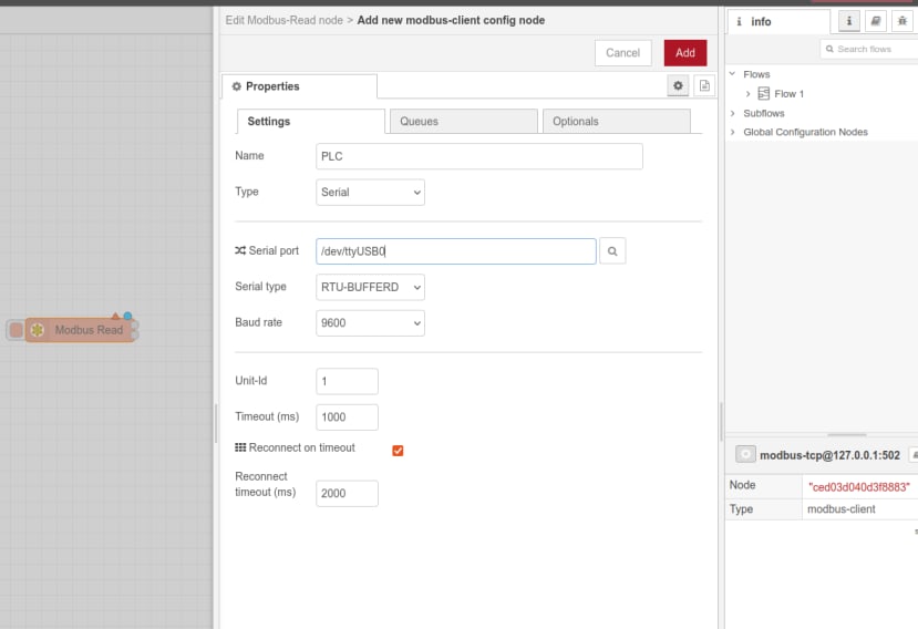
However, since a Modbus server (slave device) hadn’t been defined yet, we needed to click on edit at the side of the bottom field in order to define one. From here we set the name to PLC, selected type Serial (Modbus TCP can also be used), entered the serial port, baud rate and Unit-Id (PLC Modbus address) as covered earlier. We can also set timeouts and other optional parameters.
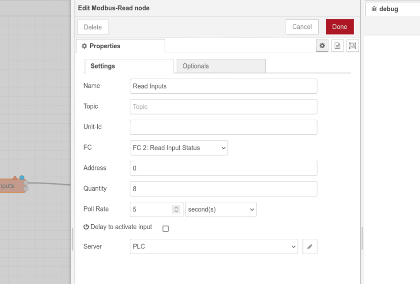
Returning to our Modbus Read node we can see the address and quantity set, a poll interval of 5 seconds, and the PLC Server selected which we had previously defined.
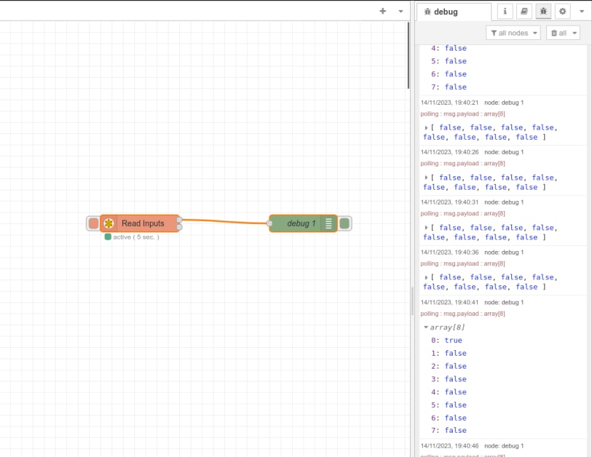
With the output of the Modbus Read node connected to a Debug node, we can see that the former is marked active ( 5 sec. ) and debug messages are output on the right. In this output we see an array of 8 values, which are all false, with the exception of the first value briefly toggling to true as Input 1 on the PLC is pulled high by connecting a wire from it to +24V.
Writing to an output
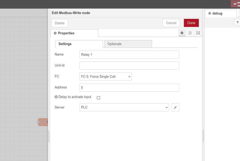
A Modbus output is termed a “coil”, as in a relay coil, and we can force its status to on or off using Function Code 5. We started by dragging a Modbus Write node onto the canvas, setting its name to Relay 1, selecting FC 5, and PLC again for the Server.
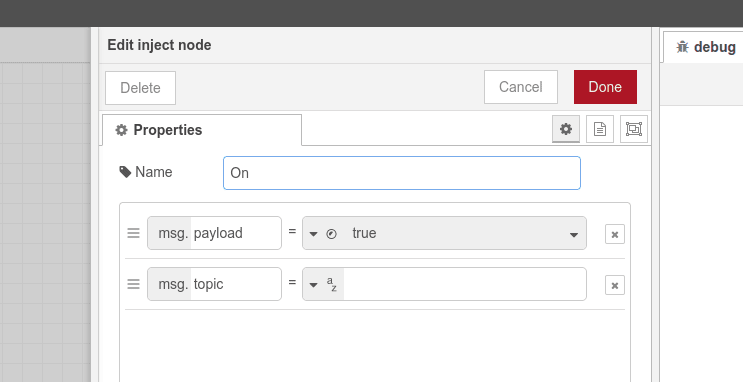
We then added an Inject node called On, set msg.payload to boolean true, and connected the output to the input of the Modbus Write node.
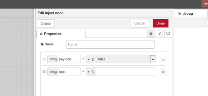
Next we added a second Inject node called Off, with msg.payload set to false and its output also connected to the Modbus Write node.
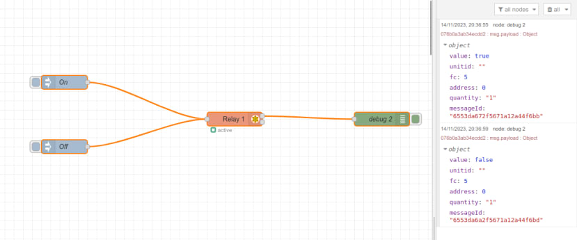
Finally, we connected the output of the Modbus Write node to another Debug node. Now when we clicked on the On inject node, we could hear a PLC relay toggle and in the debug output we saw a status of true reported. Clicking on the Off inject node we heard the relay toggle again and, as expected, a value of false was reported in the debug window.
Final words
In this series we’ve seen just how easy it is to combine the industrial convenience of a low cost PLC with the power of a Rock SBC, and how quickly we can be up and running with an incredibly flexible software platform such as Node-RED, reading inputs and driving outputs. We’ve not even scratched the surface of what’s possible with Node-RED, which enables rapid development of complex applications, plus integration with databases, web APIs and much more.
Furthermore, with a powerful embedded compute platform such as a Rock SBC, it would also be possible to run advanced machine vision and AI applications, which are similarly integrated with industrial platforms via a PLC and Modbus interfacing.