Edge Enabling a PLC with Rock Part 1: Introduction
Follow article
 Dave from DesignSpark
How do you feel about this article? Help us to provide better content for you.
Dave from DesignSpark
Thank you! Your feedback has been received.
Dave from DesignSpark
There was a problem submitting your feedback, please try again later.
Dave from DesignSpark
What do you think of this article?
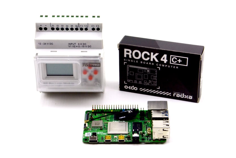
Using a Rock 4 C+ to edge-enable an RS PRO PLC for smart automation.
In this series of articles we take a look at how a low cost RS PRO programmable logic controller (PLC) can be combined with a Rock 4 C+ single-board computer (SBC), to create a powerful edge compute enabled platform for industrial automation.
Flexibility + industrial I/O
Linux SBCs have a vast ecosystem of open source software available to them at no cost, a great deal of which can be put to use in applications such as industrial automation and building management; from the many programming languages and powerful libraries, through databases, messaging platforms and security tools, to machine vision and AI frameworks.
However, most SBCs lack I/O suitable for interfacing with industrial sensors and actuators. Meanwhile simple PLCs which feature industrial I/O have been ubiquitous for many years and are low cost, but typically only support basic ladder logic programming. However, it is common for such PLCs to support Modbus communications and this can be used to interface with a single-board computer such as a Rock 4 C+, which can in turn host far more advanced applications.
In combining an SBC and PLC in this manner, the latter essentially becomes an I/O expander, which provides some degree of isolation and takes care of switching higher voltages and currents.
Hardware
Next we’ll take a look at the hardware that we will be using and the rationale for choices made.
Rock 4 C+

There are a variety of options available to us in the Rock family of SBCs, at the time of writing ranging from Rock 3 Model C with 1GB RAM, all the way up to Rock 5 Model B with 8GB RAM. Any of which would provide a significant increase in resources over those provided by a simple PLC and be more than capable of running many typical Linux-based applications.
In the end the Rock 4 C+ (249-3158) was decided upon, as its RK3399-T SoC (Dual Cortex-A72@1.5GHz + Quad Cortex-A53@1.0GHz CPU) should provide all the compute performance we’re likely to need for the applications that we have in mind, while 4GB RAM will mean that we can comfortably run numerous apps side-by-side. For example, we may have our control logic, a database for logging historical data, plus a web interface for data visualisation and analytics.
That said, with careful planning and perhaps some optimisation it should be possible for numerous applications to coexist on a Rock 3 C with 1GB RAM, provided none of them are particularly compute or memory intensive.
RS PRO PLC
RS PRO offer a simple, easy to use PLC range comprised of:
- Logic module with or without LCD screen
- I/O extension modules
- RS485 communications module (917-6392)
- USB cable (917-6395)
- Memory module (917-6399)
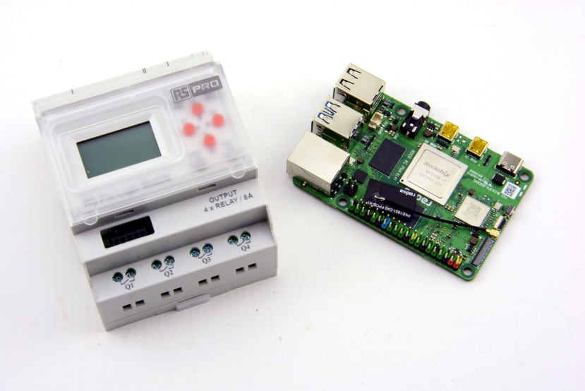
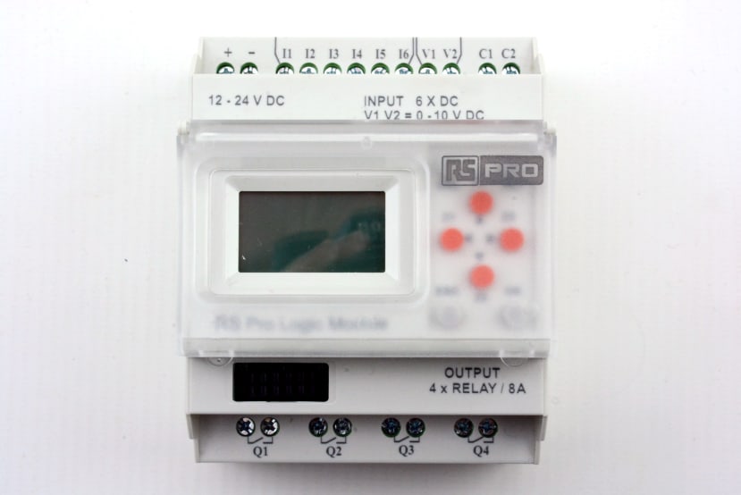
The base logic modules are available in variants with either LEDs for I/O status or an LCD screen, and either 110-240VAC mains input or 12-24VDC powered. All models have 4x SPNO relay switched outputs rated at 8A @ 240VAC / 30 VDC (resistive), plus 8x inputs. Depending upon the model, inputs are either 8x digital, or 6x digital plus 2x analogue (which can be used as digital).
Each I/O extension module adds another 4x relay outputs, plus 8x inputs. Up to 3x extension modules may be configured, for a total of 16x outputs and 32x inputs.
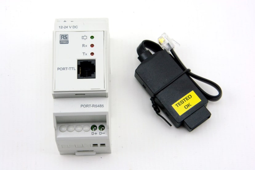
An RS485 communications module is available for integration as a Modbus RTU slave. While logic module variants with an LCD screen may be programmed via this, a USB cable is available for use with desktop programming software. However, this cable can also be used for Modbus communications, with the USB interface appearing to the host computer as a regular serial port.
The memory module is used for transferring ladder logic programs from one PLC to another.
For the logic module it was decided to go with the model which has DC power input and an LCD screen (917-6370) . However, any of the current RS PRO logic module variants would have sufficed and it’s possible that a simpler variant, without an LCD screen, might have been more convenient for the intended use case, as the LEDs would have provided I/O status indication at a glance.
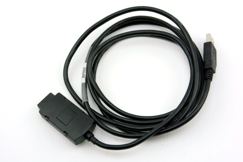
The USB cable will be used at least initially for Modbus communications.
Modbus

Example of Modbus architecture. Modbus Organisation, CC BY-SA 4.0.
Modbus is a client/server communications protocol designed for use with PLCs and which has been around for over forty years. It may not be the most fashionable or feature rich of fieldbuses, but it has stood the test of time as a simple and reliable means of integrating industrial automation components. There are a number of different versions and Modbus TCP for example can run over TCP/IP networks, but here we are concerned with the classic Modbus RTU implementation, which employs a binary format with error check mechanism, over serial communications.
With Modbus RTU a single serial line can have a maximum of 247 slave devices, each with a unique address, to 1 master. Modbus operates using a function code (FC) which defines what we want to do. For example, FC5 is “write single coil”, which we can use to force a PLC output to an on or off state. The function code plus data — e.g. the register address for the output we want to control and the desired state — are combined with the target device address and a cyclic redundancy check (CRC) for detecting errors at the receiving end, to create a Modbus serial line protocol data unit (PDU) which is transmitted on the bus and acted upon by the slave.
We’ll mostly be interested in the aforementioned FC5 function code, along FC2 “read discrete input”, which we can use to set PLC outputs and read inputs. However, there are other function codes which we could make use of, such as FC6, which allows us to write to a “holding register”, which might be used to store a parameter in a PLC program, such as a timer value. Hence, one additional possibility is to also employ a sort of hybrid approach, whereby a PLC program takes care of a main control loop and an attached SBC updates timer values as and when required.
Coming up
In Part 2 we’ll cover Rock 4 C+ software installation and PLC configuration, and provide a demonstration of reading inputs and writing to outputs using Node-RED.
Disclaimer
This series of articles describes the construction of a simple proof of concept only. No warranties, express or implied, of fitness for a particular purpose are made. It is wholly the responsibility of those implementing solutions to ensure that they meet all applicable regulations and standards.
Comments