DesignSpark Mechanical - Mirror symmetry with construction line
Follow article
 Dave from DesignSpark
How do you feel about this article? Help us to provide better content for you.
Dave from DesignSpark
Thank you! Your feedback has been received.
Dave from DesignSpark
There was a problem submitting your feedback, please try again later.
Dave from DesignSpark
What do you think of this article?
Our DSM community expert and power user, Smithy demonstrates how a simple construction line can be used to create mirror symmetric objects and manage the linked face associations in this 2-part video series. Whilst DesignSpark Mechanical (as of v5.0) lacks a one-click 3D mirror tool like traditional CAD software, there is still a lot you can do with a construction line mirror. Note that DesignSpark Mechanical Version 5.0 (Build 7232) is used throughout this demo. Chapter timestamps are embedded in the videos.
Part 1: Creating simple mirror symmetric objects
Part 2: Manage linked face associations and Advanced tips for Drawing add-on users
Essential Quick Tips - for printed reference:
The following Quick Tips lay out the essential creation principles of simple symmetric 2D shapes, pulled into a symmetric body with the description of necessary processes to add further symmetric features.
For more information, download our in-depth article.
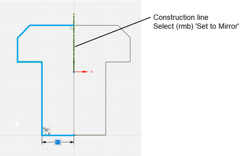
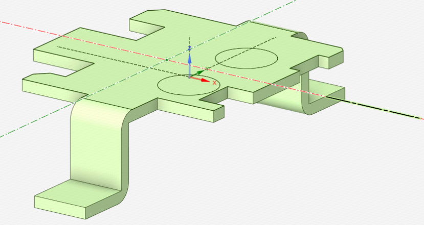
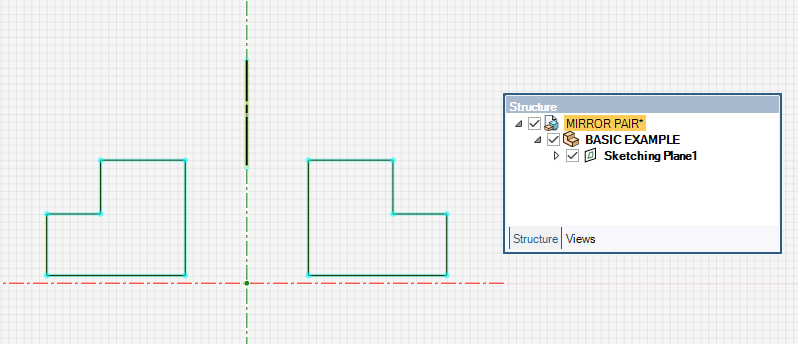
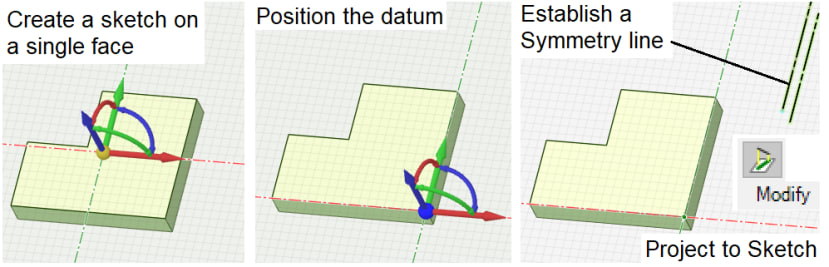
Tip #1: One axis Symmetry
Draw shape to complete a profile and exit sketcher.
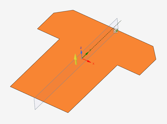
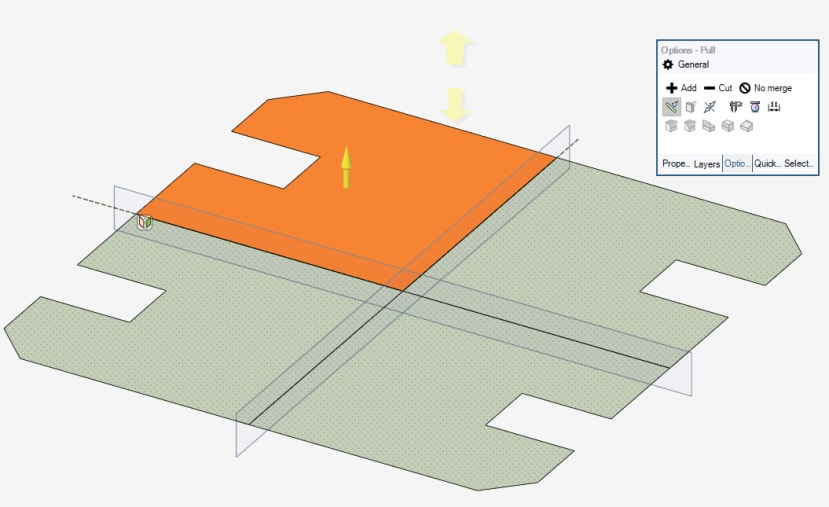
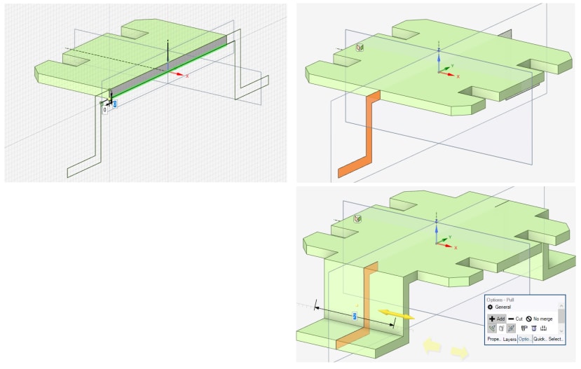
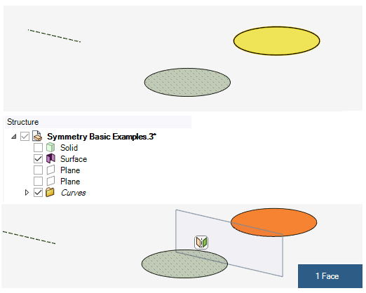
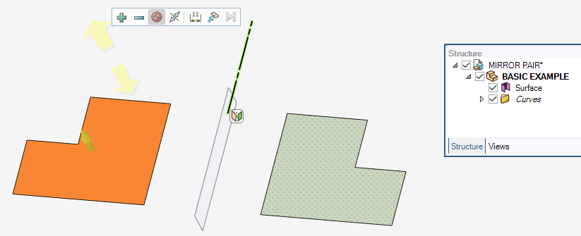
Tip #2: Surface into a Body
i) Select the surface (note the Mirror Plane and its icon - select it to disable mirror symmetry face linking process)
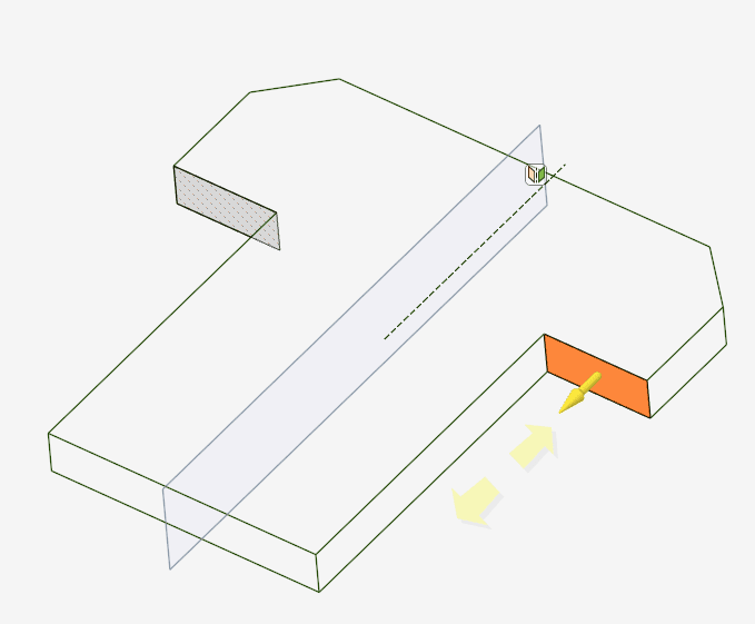
ii) Pull Surface to thicken and create Body
Note the display of Mirror plane with able/ disable toggle and the texture highlighting of the 'associated linked face' upon any linked face selection.
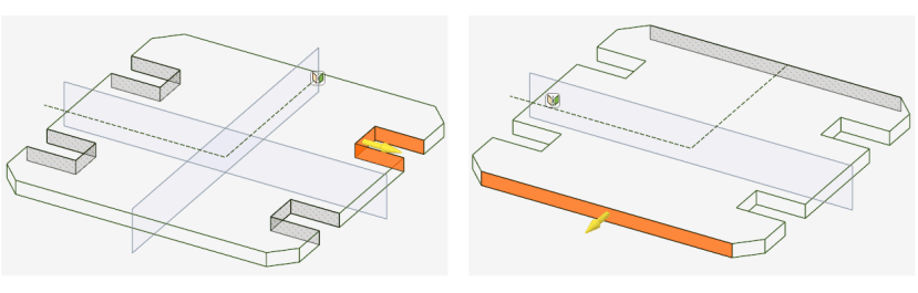
Tip #3: Two Axis Symmetry
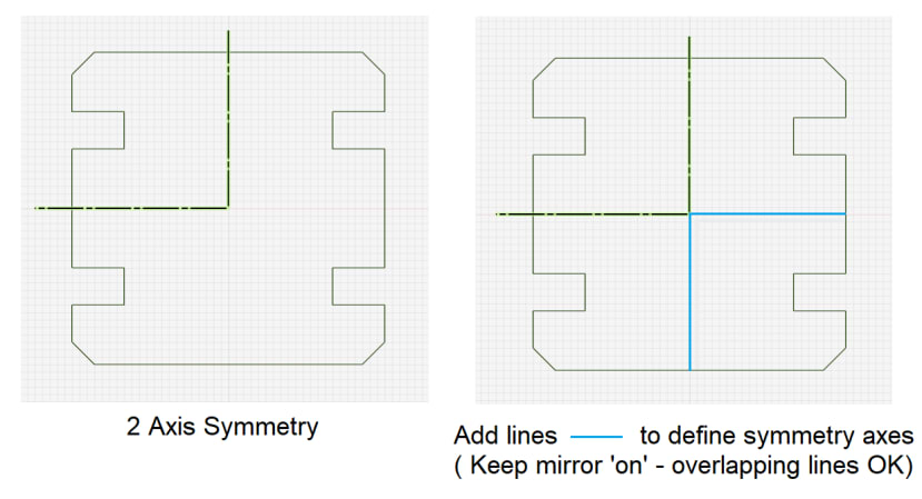
Exit sketch. Note the 2 mirror planes and the divided overall pattern.
Select only 1 reflected segment - Pull to thicken with merge on
Note the one or two plane symmetric highlights
Tip #4: Adding Protrusions or Depressions
To an internal existing face edge
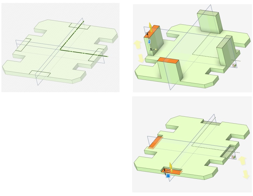
To an external existing face edge:
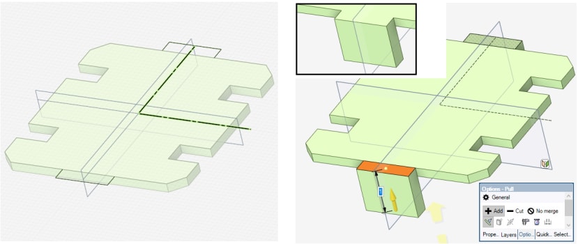
Using a sketch plane through material thickness:
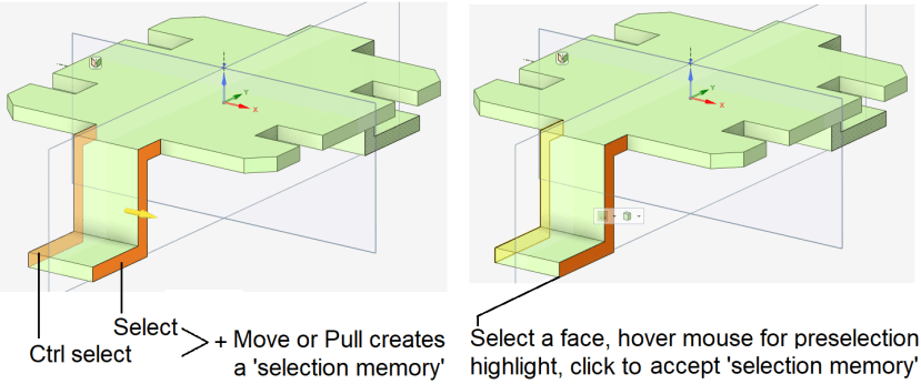
Tip #5: Selection Memory
To establish / recall a selection memory of faces (very beneficial when combined with Mirror / Symmetry Planes)
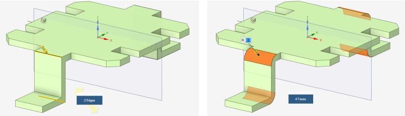
Tip #6: Create duplicate features
Such as rounds / chamfers over mirror planes
Tip #7: Mirror / Symmetric Feature ( selected ) Deletion
i. Select the face/faces > Cut and paste
ii. Select the face/faces > Pull with mirror plane disabled

Tip #8: Mirror / Symmetry Axis Deletion
Select any face to 'show ' the relevent Mirror Plane > select the plane > Delete
Tip #9: Mirror / Symmetry - Disabling the Default Behaviour
Select the face/faces > Pull with mirror plane disabled
Thus the pulled faces will not have any mirror symmetry linking and the pulling process will not establish any other linking throughout the body.
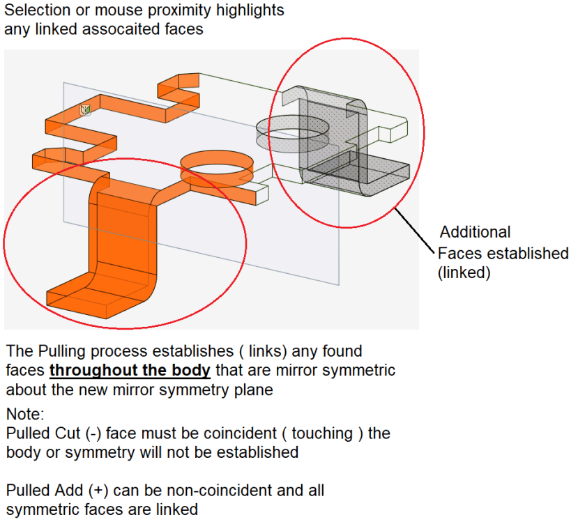
Tip #10: Mirror Symmetry - Re-establishing / Creation of Face Linking Associations
Done through a new mirror symmetry creation process which auto-associates and links symmetric faces found about the new mirror axis during the pull operation
1) Same sized and symmetrically faces disposed about the new mirror axis
2) Aligned face 'edges' across the new mirror axis.
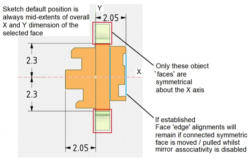
Tip #11: Observations on Sketch plane default XY position
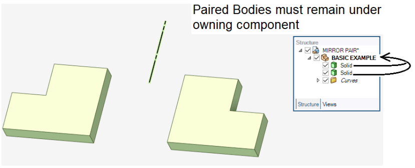
Note: It may be desirable to keep the original Mirror sketch lines in a Curves folder with the body - Creating the body in a component will achieve this.
Create a sketch plane on the above selected face.
Add a construction line to the X axis, set to Mirror and draw a circle
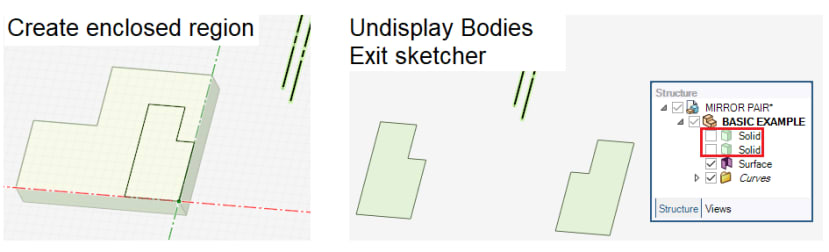
Sometimes, it's necessary to remove the Body from the display, prior to exiting the sketch (mirror on).
Display the Body, Pull cut ONLY ONE of the circles into the Body
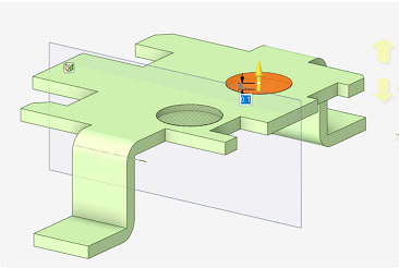
Establishment of new with additional pre-existing symmetrical faces are now associatively linked.
Tip #12: Example of Aligned Face Linked Pairs
Face Edge Alignments - Established throughout the body when any face is similar in size and mirror symmetrical about the face pull mirror axis.
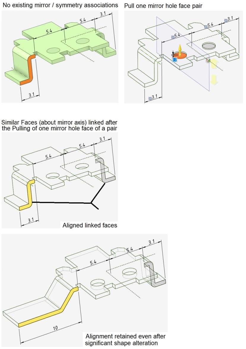
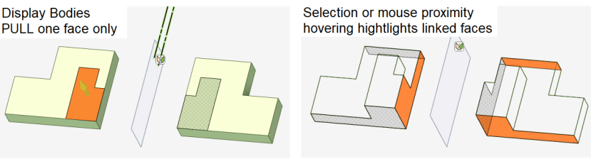
Tip #13: Handed Pair Bodies
Sketch ONE SIDE ONLY with the mirror line set on
PULL one face only
Tip #14: Adding features / further designing
*Important note concerning the functionality of adding mirror symmetric protrusions , depressions, holes etc. If not functioning as described:
1. Before exiting the sketcher, undisplay/hide the body.
2. Exit the sketcher (profiles must in this situation be closed)
3. Display the body, select a face, then pull, etc
Comments