DesignSpark Mechanical - Detailing options and Model-based definition
Follow article
 Dave from DesignSpark
How do you feel about this article? Help us to provide better content for you.
Dave from DesignSpark
Thank you! Your feedback has been received.
Dave from DesignSpark
There was a problem submitting your feedback, please try again later.
Dave from DesignSpark
What do you think of this article?
Many images and GIFs have been created to illustrate various aspects of the software, so please allow some time for this webpage to fully load in your web browser.
Preface:
2D drawings have been the backbone of communication ever since an idea needed to be saved - it goes back a very long way...

To define a part, dimensions (features of size) and notes are combined with Geometrical Dimensions and Tolerancing (GDT), which in totality quantify permitted errors of inaccuracy in manufacturing, thus producing an economical part meeting design criteria.
Dimensioning and applying GD&T is the mechanical universal language understood by specifiers and manufacturing engineers. An intentioned imprecise, wide tolerance and lowest cost part, requires similar specifying as a precise, narrow tolerance and high-cost part.
The latest offering in Mechanical CAD is Model Based Definition (MBD). 3D models having Geometrical Dimensions and Tolerancing (GD&T) with Process Manufacturing Information (PMI) applied directly to it as a way of imparting information to reduce / negate the requirement for 2D drawings.
DesignSpark Mechanical provides both traditional 2D drawings, annotating with GD&T symbols (annotation and encoded sematic types) and 3D MBD based on the American standard ASME Y14.5 (2009) and Y14.41 with symbol encoding semantic creation methods. Semantic encoding guides the correct symbol formulation which assists in understanding GD&T underlying theory and principles.
Drawing annotations can be set to default ASME, ISO, JIS and GB standard styles.
Multi-national and major manufacturing organisations have very efficient 'data' information paths - MBD data minimises product definition time thus shortening time to production. It should be noted that small manufacturing companies may not have the technical skill nor the technology to exploit MBD data, therefore the traditional 2D dimensional and noted drawing with GD&T definition is still necessary to fully define the component. It is envisaged that a part drawing (paper or image) supplied with a 3D model (STEP file) will be common practice for the foreseeable future.
Drawings contain additional information beyond the part form.
2D drawings can in addition to the above, define all supplementary manufacturing information needed to manufacture the part. Information such as specific part material characteristics e.g. Fibre direction / areas of hardness or softness / plating / post plating machining /sand ~ vapour blasting /painting areas, in-process part dimensions, inspection set-up datum targets are a few common aspects of mechanical part manufacturing information that can be easily defined or referenced in a drawing with notes and additional dimensions for explicit communication. Also, drawings with separate ( scalable / detail / broken ) aspect views, may better emphasise to the viewer, particular individual or related requirements in preference to an on-screen 3D part / assembly model.
The way a drawing is set out and depicted with defining symbols isn't part of this article. Dimensions, tolerances and GD&T symbols all require understanding and application principles.
Here are the key features and benefits of the DesignSpark Mechanical Detailing feature set:
-
Custom Formatted Drawing Sheets with user set custom document properties, assisting drawing creation, and model document - sheet associations.
-
Internal Components vs External Referenced Components and their associated Drawing Sheets in assemblies. Two alternative working methods compared (benefits and limitations) for prototype development through to production documentation.
-
Predefined or Custom View /Views Sets : Part or Assemblies, Hole or BOM Tables.
-
Bi-Directional flexible Model-Drawing-Model Associations with dynamic driving dimensions.
-
Quick access to Internal Parts / Part Features in complex assemblies.
-
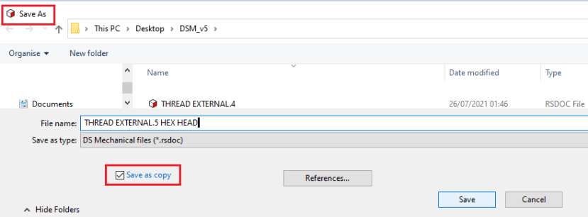
Quickly create New Documents (Model and Drawing) from similar part derived information using 'Save As' with copy.
-
Machine Thread Generator (Standard and Custom).
-
Model Based Definition (MBD) through semantic (ASME principled) GD&T / Datum Targets with Drawing Annotation settings for ASME, ISO, JIS and GB standard styles.
If you want to read in a different order and need to access this list for navigation, click the icon next to any key feature to jump back here.
Custom Formatted Drawing Sheets for company standards and logo with definable input fields for repeated / efficient standard data entry and notes. Example GIF below showing Title block set as file name with Material and Coating information cut and paste from a preferred material / process list, other text, select field and enter text. Text position and size is set in the custom format sheet.

Custom Document Properties e.g. 'Used On' and 'Similar To' created in the drawing custom sheet with assigned / associated text fields can by manual entry, record documents, facilitating file search and load. Custom document properties are user definable and may list e.g part material, drawn date, drawing issue, etc. See example in GIF below:
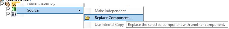
Change Control. Alterations auto propagate on 'save' to all external inserted files within other files (assemblies). Alternatively, for manual individual external file replacement (exchanging inserted file source), choose file 'save as' with copy and replace original file. This facilitates document history and retrieval processes.
Example of 'save as' files...

Internal Components vs External Referenced Component files in assemblies.
Internal Components and their Drawings: During a new design process, usually sketches make faces and faces are pulled into bodies which can be added to or removed from other bodies and made (moved) to a new component. Bodies and components can be moved/ re-ordered, deleted and combined with other bodies of different components as the design evolves.
Working only with Internal components, there is total freedom to change anything; you can completely reorder the design and its structure etc. is wholly contained within the (parent) file upon saving.
Bodies and their owning Component together with their data are Internal to its parent file and any associated Drawing Sheet attached to it, even if opening the component (recommended), resides wholly within the parent file allowing one convenient file data location with model /drawing change management convenience.

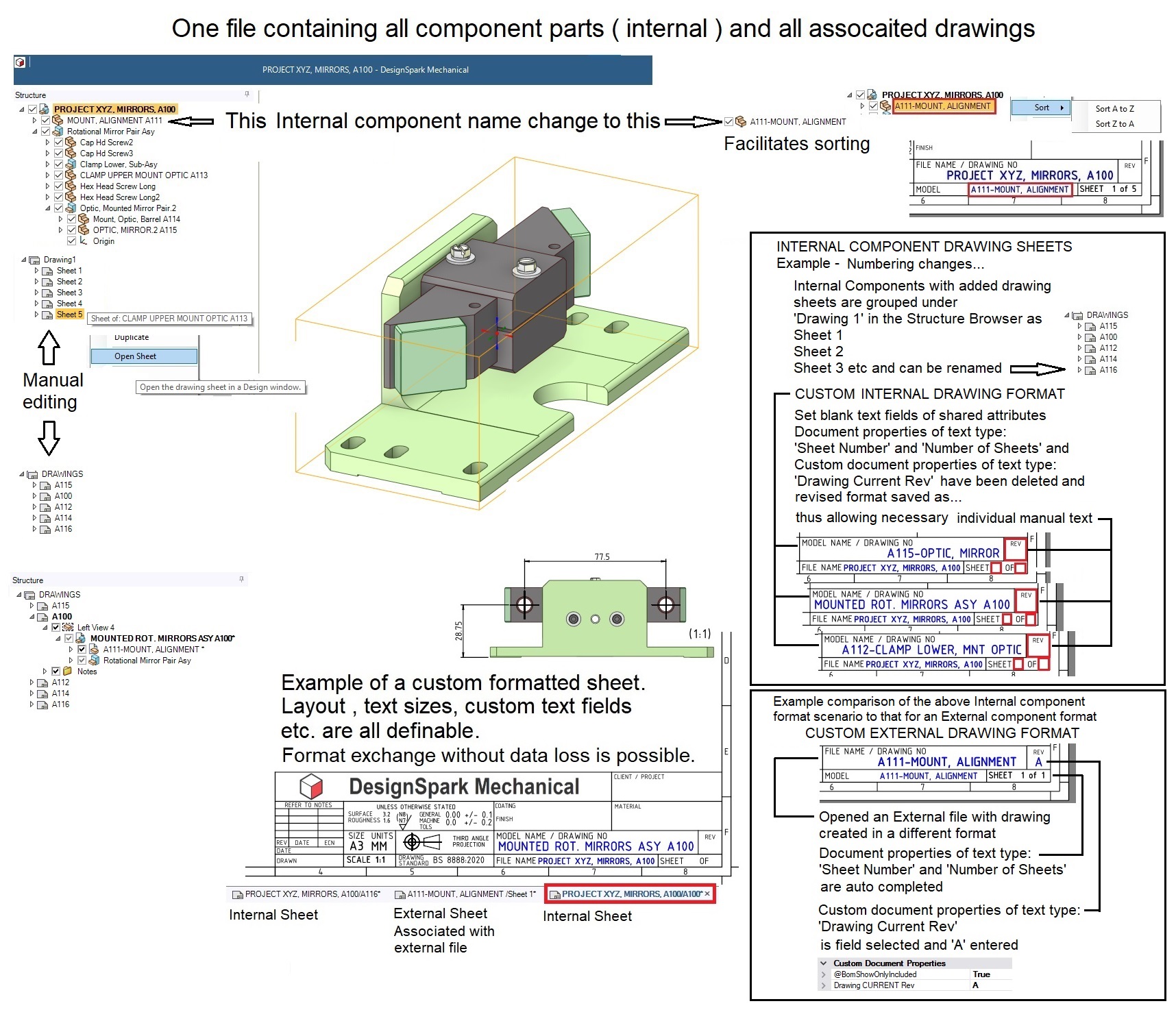
When a component is opened, all the drawing sheets of its parent file are also shown - this facilitates convenient opening to reference drawings dimensions or notes, the latter may be copied and pasted for drawing creation efficiency. See image above.
Adding new drawing sheets to Internal components (open each component to add the new sheet) adds a new sheet to the parent file - hence the structure browser reports Drawing 1... Sheet 1, Sheet 2 ... Sheet 5 however this can be fully manually edited for selection / opening as shown in the below image.

Notes on copying External Components and their existing associated Drawing Sheets.
Any imported external component with a subsequent change of 'source' command>Use Internal copy, will also copy-import any associated drawing sheet with the Structure Browser showing as 'Drawing 1 (or 2, 3 depending on original Component/Sheet save)'...Sheet 1 - renaming is advised.
The copied external files custom document information migrates into custom component information as it has lost its original document. Any drawing sheet copied will transfer with its original sheet format - this format must be deleted and replaced for an Internal component format or upon data entry in its pre set text fields, this data will populate to all other internal components (document property) incorrectly, necessitating an incorrect and unnecessary search and deletion of document property fields.
Note the formatted drawing sheet shown below, has itself been externally referenced, however it may be removed with the drawing sheet having no format, or again, the sheet can be formatted to any style with its file on disc location located anywhere for convenience. Individual drawing information, e.g. material, finish or drawing revision control is by manual text entry only otherwise group drawing information, (commonality across all drawing sheets) i.e. material, finish or drawing revision control etc will propagate to all sheets of the 'Drawing 1' - custom sheet format or no format etc. controls this behaviour.
Manual standard inputs (probably different information required for each sheet) can be accelerated by cut and paste techniques. Structure Browser standard sheet information, are all edited manually / renamed.
Note: Although when saving the parent file, the drawing sheets may have different drawing revs - it is not possible to save individual components and their associated drawing sheets together at particular revisions, as all drawings are owned by the parent file - that fact alone would in many situations restrict Internal components to prototyping / development.
It is recommended that if an Internal file with a drawing is likely or intended to be converted into an External reference file with its own associated drawing at some future time, and if wanting to preserve the dimensioning (considered only beneficial with numerous complex details), its body dimensions with tolerances are made in annotation planes on the opened component. These then can carry over when making the component external and can be used in drawing views without the necessity to duplicate all dimensioning. It is also recommended to consider making the component external after designing is finished for change management / model and drawing individual filing i.e. for production manufacture or outsourcing.
If requiring single component files with associated drawing sheets, allowing the saving and retrieval at particular issuing points, convert all Internal components into External components, opening each individually and add a new drawing with a custom format.
Drawing Notes may be cut and pasted between Internal and External drawing sheets and copied from other text files.
An Initial Internal component with an associated Drawing sheet, may still be converted to an External file and its Drawing sheet can still remain within the original parent file with model to drawing associative link intact, but this is not recommended although possible.
External Components and their Drawings: During the design process, other existing components may be imported into the active file, known as an External Component referenced file, it may be (if not locked), modified with all of its (un-opened/ potentially unknown) on-disk Instances simultaneously changing on saving, so care is required...If making an Internal copy of an External component (say a small variation is required), this solves the file linking but increases the file data size.
Files consisting of an assembly with many External component references, are data small compared to assemblies with Internal components partly due to the drawing sheets being separated / isolated from its External component model instance. Opening the External component is required to view its drawing.
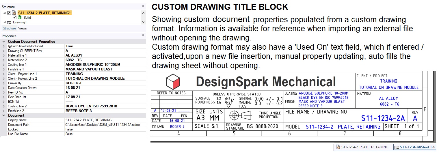
Drawings of External components can contain more part / drawing data - entering data into the preformatted text fields defined in the custom formatted sheet, recreates entered data into the document properties, which upon either importing an external component or opening the file, presents the data entered into the sheet even if the sheet isn't open ( displayed). See below image.
Note, an existing Internal component may be opened and converted into an External referenced file, or vice versa, an External file copy converted into an Internal component or group of Internal components (assembly).
An RSDOC file can have Custom Document Properties assigned and each / any Component may have Custom Component Properties assigned to it (e.g. material / mass). Adding a new Drawing Sheet (suitably formatted) will upon text field activation, populate the RSDOC file Custom Document Properties e.g. Material / Finish / Plating /Drawn By/ Release Date / Revision ID etc.
External single component files offers the ability, using 'Save As' to keep records of documents, thus storing 'As built' states and also facilitates the searching of files.

Summary on referencing Formatted Sheets.
The ability to have specific various Sheet formats to optimise data input, specific process notes, tolerances etc differentiating e.g. between 3D printing, PCB's, welding, moulding, machining, casting, sheet metal parts and assembly drawings etc, is an efficient way to standardise output information.
As technology changes, so does process standard specifications / tolerances etc. This requires the continual sheet format updating as time progresses. By making new sheet formats and referencing these in your latest projects, this ensures older projects with referenced sheet formats remain unchanged.
Note: Change any aspect of a formatted sheet and where ever it's referenced, the change will replicate automatically.
Sheet formats are interchangeable with no loss of information providing each sheet format has the same pre set text input fields somewhere within it.
Predefined or Custom View /Views Sets of parts or assemblies, dimensions, standard symbols and note annotations to industry / national standards. Hole tables, BOM tables with auto ballooning etc.
Example GIF demonstrating a dynamic Hole Table:
Size (including identifier) and quantities with positional association are automatically and adaptively recorded. Editable entries - Column and Row insertion. Selected Base line GD&T hole and position dimensioning.

Exploded Assembly - Items manually positioned in a copied file. External component associativity i.e auto updating - shown with BOM. See example in GIF below:

Bi-Directional Drawing Dimension to Model Association is through drawing view definition dimensions, irrespective of model creation method, when combined with move and pull commands.
Considerations on 'Detailing'... Dimensioning and tolerancing is the last 'design' activity prior to releasing drawings for manufacture. Creating drawings with minimum views and pertinent dimensions is 'usually the last but very necessary thought' about manufacturability - with dynamic Move and Pull operations using drawing created (or inherited annotation plane) spark dimensions, any feature (odd thickness etc.), may be dynamically tweaked to size easily in drawing views, without recourse to model creation process. Aspects considered such as, engineering preferred numbers, rounding numbers, amend for existing gauging, amend geometry to mid plane tolerance for CNC machining are just some aspects of 'detailing' requiring model geometry alterations that can be accomplished in drawing views. Demonstration in GIF below:

Quick access to Internal Part / Parts Features (for Move / Pull / Measure actions as an example) through leveraging defined drawing views and sections of parts or assemblies in custom displays of show on/ off parts, combined with layer visibility.
Example GIF below shows 3 different views plus an overall view (each in window) of an assembly in a Drawing Sheet. Object move tool can be accessed in any independently manipulated (whilst in command) view. Viewports are saved and recalled on opening file.

Fast new document (model with drawing) based on information derived from similar part using 'save as' with copy.
New file documents (model with a drawing) may be quickly created from source (seed) documents; Simply make the design change (only new geometry needs dimensioning) and file using 'save file as' with copy checked -> enter a new document name -> new document (model and drawing) is created.
Example GIF showing copied and modified document (model and drawing sheet) - adding a hex shoulder:
Machine Thread Generator:
- Cosmetic 3D model thread depiction - Dialogue input for standard / custom Major and Minor thread surface generator (Blind and Through holes).
- 2D standard thread depiction graphics.
- Various thread forms.
Example GIFs of modelling standard typical tapped holes - Blind and Through:
Example GIF of dimensioning the above:

Example GIF of ISO external thread form. Custom threads require minor diameter specifying.

Model Based Definition (MBD) through semantic GD&T and 3D dimension annotations can provide greater clarity of datum / control features over 2D drawings for in-depth 3D appreciation / visualisation. Allows the reuse in any 2D drawing view.
Example GIF of creating datums with an associated slot dimension:
Example GIF of creating / placing a compound Form and Orientation frame with editing:

Example GIF of various selected GD&T symbols (ASME) showing graphical associations between workspace and structure tree for clarity:

Any existing information may be reproduced in a 2D drawing and displayed (automatically re-orient) in any selected or new view for clarity. See demo in GIF below:
Example of MBD use (in GIF below):
Change dimensions and GD&T values -> Highlight GDT symbols Datums A, B, C -> Change view to Hidden Line Removed with Lineweight on to apply Line style and thickness options -> Select an edge changing to black override.
Additional Reading:
Learn how to customise a title block and reuse document properties in this tutorial - https://www.rs-online.com/designspark/designspark-mechanical-add-ons-customising-a-title-block-and-reusing-document-properties
Comments