Designing a laser cut case for the Raspberry Pi Touch Screen
Follow article
 Dave from DesignSpark
How do you feel about this article? Help us to provide better content for you.
Dave from DesignSpark
Thank you! Your feedback has been received.
Dave from DesignSpark
There was a problem submitting your feedback, please try again later.
Dave from DesignSpark
What do you think of this article?
Rapid prototyping with DesignSpark Mechanical and a laser cutter
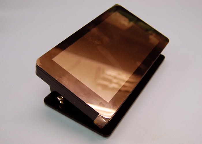
The Raspberry Pi is a single board computer that surprised the world by selling over 500,000 units in the first two weeks, and over 5 million to date. There is now an official Raspberry Pi Touch Screen to go with it, providing a high quality display with multi-touch capabilities. Like the Pi, the Touch Screen comes without a case, requiring mounting for practical use. Though there are cases available to buy, there is nothing quite like designing and making your own solution to a problem.
This post covers how DesignSpark Mechanical – a free-to-use CAD package from RS – can be used to design and produce files suitable for laser cutting. Recommended reading includes other posts about DesignSpark Mechanical: an introduction to CAD/CAM and laser cutting. The design file is shared at the end of this post.
From 2D to 3D
A caveat is that I am a novice in the world of 3D CAD. With plenty of experience designing in 2D for laser cutting sheet material, I am still finding my feet when it comes to modelling in three dimensions.
Familiarity with laser cutting is the reason I wanted to make a housing from laser cut parts. Another factor is that laser cutters are becoming increasingly common in hackspaces, Fab Labs and other shared workspaces, making them both accessible and affordable to use. Other solutions may have been to 3D print or CNC mill an enclosure.
Being familiar with a certain tool or software and method of drawing can often make it hard to change habits or ways of thinking. I began this project by drawing shapes as I would have in 2D drawing packages I am more accustomed to. However, as I continued to discover new tools in DesignSpark Mechanical and follow more of the tutorials, I began to experiment with new ways of modelling that proved handy, quick and compelling.
DesignSpark Mechanical
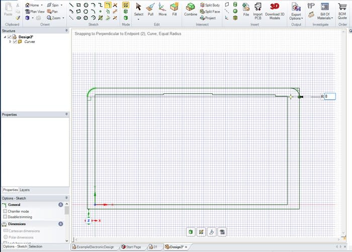
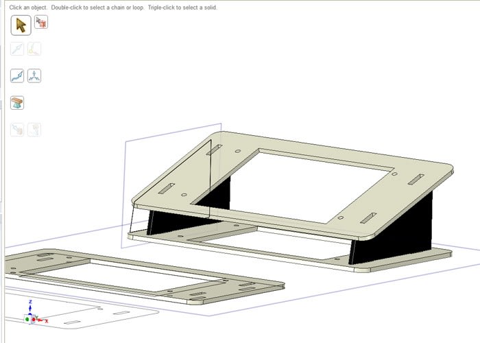
With a brief pencil sketch, the touch screen and a set of digital callipers on the desk, I began by drawing individual parts corresponding to layers of sheet stock that would stack to form the enclosure.
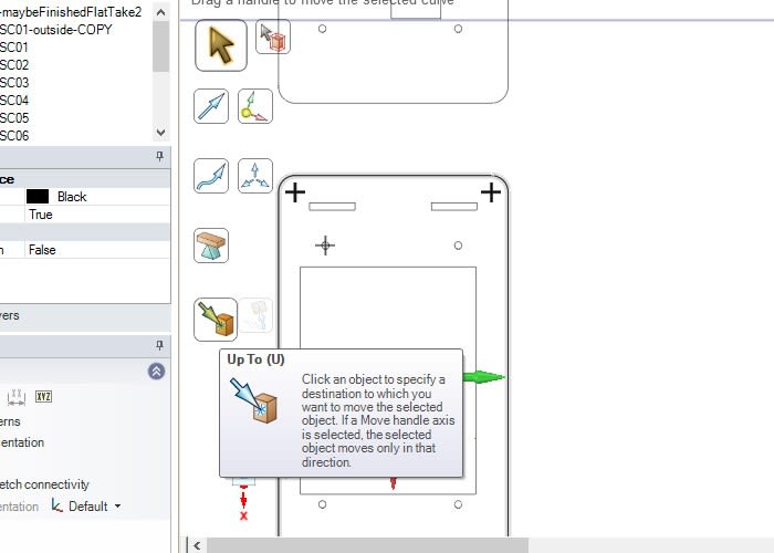
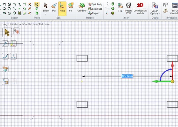
I found a combination of using the 'Up To' tool and moving objects a known distance by typing in figures whilst dragging with the mouse allowed me to draw designs fairly quickly. Once I was happy with the number of layers drawn, I extruded one by 3mm – the thickness of the sheet stock I commonly use – making a 3D object.
This 3D object was then used to help model the next part with which it needed to interface. A series of interlocking hooks and slots were designed to hold these two parts together once cut out of sheet material.
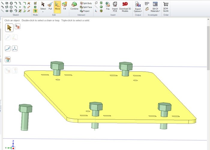
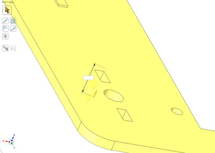
A common method of joining perpendicular laser-cut parts is to use tabs and slots with a nut and bolt. This requires a specific design that I have 'drawn' in the past by manually arranging lines in 2D CAD. For this design I decided to model some dummy 'bolts' and use them to carve or cut out the necessary holes instead.
The processes above were a bit of a light bulb moment for me and CAD – having shied away from 3D modelling for so long – I was now discovering some of the benefits of tools available and new ways of drawing that could save time and prototyping material.
With a completed design, I saved the file and exported as .dxf – a file suitable for importing into the laser cutter control software. Note that you must ensure two things before you export your file:
Firstly, each part must be 'flat' on the XY plane, so that the outline can be seen when in plan view.
Secondly, check that the drawing window is in plan view of the XY plane. This will ensure that the paths exported to .dxf are correct.
First cut
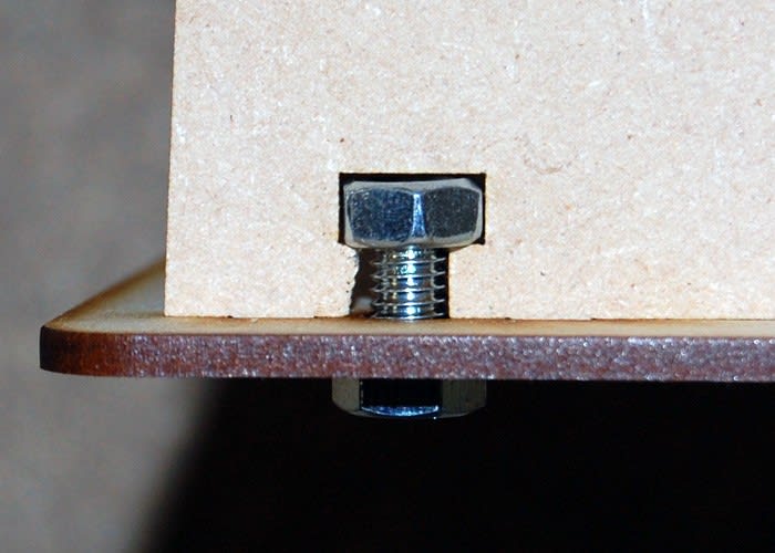
Slight modification was needed - here by cutting away excess MDF with hand tools to fit the bolt.
As usual, I cut the first revision from MDF sheet stock to minimise material cost and cutting time. The parts were offered up to the touch screen and Pi and some adjustments made where the fit needed improving. The biggest problem was where I had 'carved' the tabs and slots with 3D models of dummy bolts. These were not quite big enough and were modified using the 'Pull' tool.
With the necessary changes made, a set of parts was cut from acrylic and the housing was assembled. Hardware required for the case is:
-
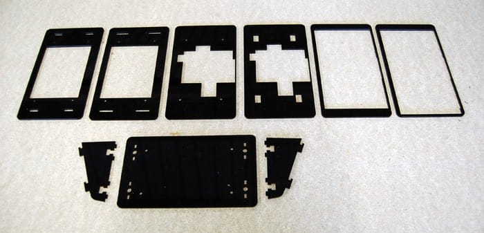
Laser cut parts from 3mm sheet stock
-
Raspberry Pi 2 + touch screen
-
4 x M6 nuts
-
4 x M6 x 12mm bolts
-
4 x M3 x 16mm machine screws
-
4 x rubber bumpers / feet (optional)
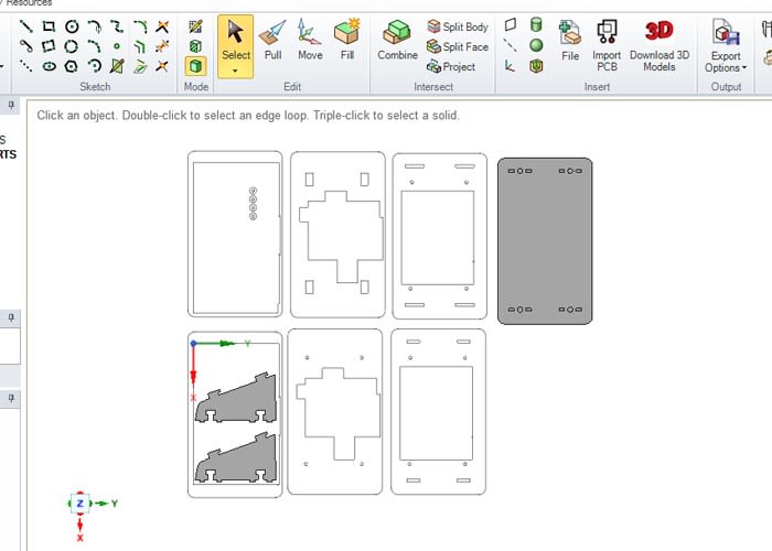
The laser cut parts consist of two main sections: six layers that stack up to form a backing to the screen and three parts that form a base and uprights to hold the screen assembly.
Conclusion
DesignSpark Mechanical is a powerful CAD package that can be used to create files suitable for laser cutting, forming a rapid prototyping workflow that enables a novice to go from screen to physical object within a matter of hours.
Once comfortable with the transition from 2D to 3D drawing techniques and new tools available, I found it a flexible and capable environment for designing the housing for the Raspberry Pi Touch Screen.
The DesignSpark Mechanical files are available from here – you can download them, modify them if you wish and laser cut your own housing.