Design Example - Pmod PCB Reference design
Follow tutorial
 Dave from DesignSpark
How do you feel about this tutorial? Help us to provide better content for you.
Dave from DesignSpark
Thank you! Your feedback has been received.
Dave from DesignSpark
There was a problem submitting your feedback, please try again later.
Dave from DesignSpark
What do you think of this tutorial?
This tutorial requires:
DesignSpark PCB V11.0.0To help you get started quickly, Pmod board outlines with connector positions marked for easy positioning are attached. To use these reference PCB's in your design please see this guide.
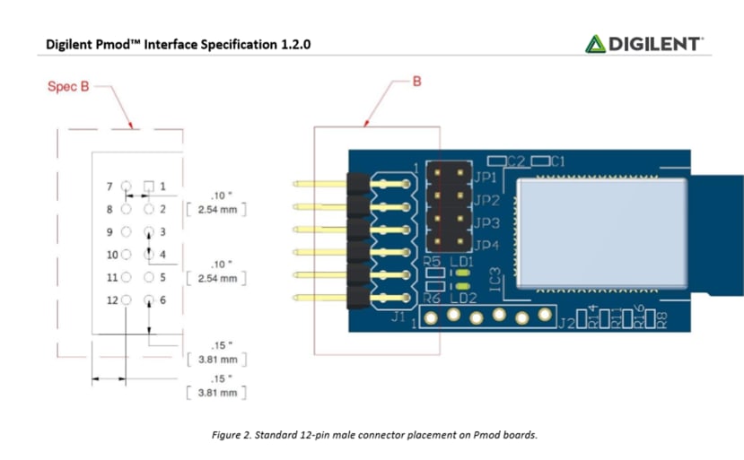
The Digilent Pmod specification provides the key details which define the connector location and board width, the length is user configurable.
Two board designs are provided, Pmod SIL (Spec A) and Pmod DIL (Spec B).
Pmod SIL (Spec A).
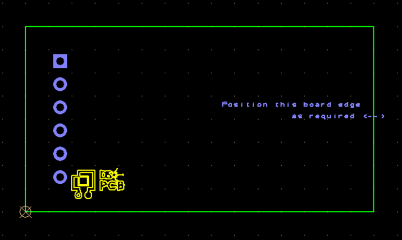
The suggested component to use as the right angle connector is (681-2537) a break away pin header strip. The component model is downloadable from the web page for the part number in the "Explore all technical documents" link using Library Loader direct to your DesignSpark PCB library.
Pmod DIL (Spec B).
This has the same board outline size as the Pmod SIL above, but uses a DIL right angle connector.
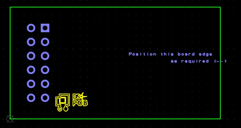
The suggested right-angle header connector can be downloaded here.
NOTE.
An important point to note is the component pin numbering.
Digilent state " Note that the pin numbering conventions for the 2x6 connectors are non-standard and are mirrored between the host connector and the peripheral board connector." This also differs from the odd/even row pin numbering that results from the use of these parts with ribbon cables.
Full details are in the specification, however this image illustrates the point.